Thanks for joining me!
Good company in a journey makes the way seem shorter. — Izaak Walton

ImportExport
Thanks for joining me!
Good company in a journey makes the way seem shorter. — Izaak Walton

In manufacturing, there are a lot of fluctuating circumstances that need to be monitored in order for a company to be successful and profitable. Companies need to be constantly working to make sure that the manufacturing side of the business is always operating at max efficiency. However, problems can start to pile up if one small snag occurs in the process along the way. For most manufacturing companies there is the engineering side, and there is the manufacturing side. The engineering side supplies the manufacturing side which in turn makes the profit. Delays with the engineering side of a business create a bottleneck & potentially cause lost profit. Here at Perception Engineering, we offer multiple different types of manufacturing support services that allow us to add engineering capacity and help keep companies moving forward. So, what exactly are these support services and how can they help? Jump into the next section of this blog to find out more!
So why exactly do companies need engineering/manufacturing support services? Fluctuation in demand & seasonality can cause work to pile up and deadlines will be right around the corner. Support services are a great option to alleviate capacity constrictions and provide a quick solution to a short-term problem. By contracting a company such as Perception Engineering, a team of experienced engineers is added to your company to tackle the problems at hand. Hiring temporary help instead of hiring additional employees can save a company money in the long run and can be a more immediate solution as hiring can be a long process. On the other hand, some companies do not have an in-house engineering team. Both long term and short term contracts can put in place to designate a company like Perception Engineering to provide engineering and manufacturing services to the company in need.

With the engineering and manufacturing field being so broad, there can be multiple services utilized within one business. One common service utilized is providing 2D drawings. Some companies or businesses do not have a set standard for a drawings template, this is where an engineering team would offer the support service of creating a standard and applying it to all drawings that need to be completed. Here at Perception Engineering, we specialize in multiple different services. These include 3D modeling, 2D drawings, new product development, plant floor layout, Reverse Engineering, product assembly, and so much more.
Engineering and manufacturing support services are a great option for companies all across the board. Whether your company has one hundred employees or only five, engineering services can provide value to your business. It is a great option to have companies like Perception Engineering that are willing to jump in when extra capacity is needed or to fill a knowledge gap.


An important variable to keep track of when engineering a part is its multiple mass properties. With varying features and sizes the mass and other linked variables related to the mass can be changed greatly with a simple edit to the design of the given part. SolidWorks offers an easy way to assign mass properties to a part, it all depends on what material is desired. This blog will cover how to apply different types of materials to a given part and how to view the mass calculated by the part size and material.
The material of a part can be assigned/changed in both a single part file and inside of an assembly. In a single part file, the material option can be found in the feature tree near the top, as shown in Figure 1 below. To apply a material, right click on the “Material” option in the feature tree and click edit material. When in an assembly file the material option will not be in the feature tree. To locate the material option in an assembly, simply right click on the part of which the material will be changed and find the material option in the menu and click on the “edit material”.

Figure 1: Edit material location
After selecting the edit material option, a pop-up window will appear with multiple drop-down menus to select what types of material to choose. The pop-up window and drop-down menus are shown in Figure 2. The most common drop-down menu to select material from will be the “SolidWorks Materials” file. Once the drop-down arrow has been clicked a wide arrangement of different materials can be selected from. All there is to do is click on a material and hit the apply button at the bottom of the pop-up window. That material and its mass properties are then assigned to your part model. All materials in this drop-down menu have preset mass properties.

Figure 2: Material pop-up window
With each new material applied to the part there will be new mass properties as well. To view the mass properties there is a mass button located on the evaluate tab. The location of this mass properties button is shown below in Figure 3. This mass properties button is in the same location in an assembly file. However, it’s the weight of the entire assembly that is calculated when the mass properties are calculated in an assembly.

Figure 3: Mass properties button location
After clicking on the mass properties button another pop-up window will appear. This pop-up window shows all the mass properties for the part/assembly that is open at the moment. The most common properties used are placed near the top of the pop-up window, they are density, mass, surface area, volume, and center of mass. For this blog part example, a small pyramid was created and assigned malleable cast iron as the material. An example of this part’s mass properties is shown in Figure 4.

Figure 4: Mass property pop-up window example
Even after features in the model have been changed and updated the mass properties of the parts can be updated simply by closing the pop-up window and then reopening it using the mass properties command button. For this example, the pyramid was given chamfers on all edges to change its appearance. By doing this the mass, volume, surface area, and center of mass were all slightly changed. These changes are shown in Figure 5 below.

Figure 5: Updated mass properties
Knowing the mass properties of a part before it has even been created in real life is a huge advantage to have when manufacturing and prototyping. This mass properties tool is crucial to have when making changes and adding updates to a part or assembly. This tool allows the creator to view how every change can affect the mass, volume, density, and even its center of mass. All these properties are extremely important when it comes to engineering the perfect part.

When working with CAD software or in the design field, it is likely you will come across files that will not be in a CAD friendly format. Customers might send over files such as PDF’s or JPEG. These are two very common file types; however, these files cannot be input into any CAD software. Most of the time these types of files that are transferred are pictures of drawings from CAD software. Therefore, it would be very beneficial to have them in a CAD file format to be able to convert them to solids or input them as a sketch. There is a way to convert these files to DXF or DWG file types. Keep reading this blog to find out!
To convert any file to a different type, a file converter is needed. If you google the type of converter that is needed such as PDF to DXF converter, plenty of online sites will show up. However, it can be dangerous to bounce around random online sites downloading files. Not only could the file quality be extremely low, but it could also expose your computer to viruses. Take some time to do some research and look for popular sites that have good referrals or sites that are verified. Below in Figure 1 are some popular and safe file converting sites.

Figure 1: Example Converter Sites
Some of these sites will offer you a limited amount of conversions before you must purchase the software. Other sites offer conversions that are totally free. It depends on preference and file type what site will work best for you and your file needs.
For an example conversion, the CAD soft tools link will be used and shown how a typical conversion is done. For this example, a PDF to DWG converter will be used. To find the correct site “CAD soft tools PDF to DWG” is typed into google. The first site link is the correct one. After the link is opened the converter and options will be brought up. CAD soft tools PDF to DWG converter is shown in Figure 2. Under the select PDF option click on choose file, this allows you to browse your computer for a file. After selecting the correct PDF file, an email is entered to send the DWG download link to. A receiving email is entered to retrieve the link at. After the consent option is checked and the convert button is hit the file will be converted and a link sent to the corresponding email.

Figure 2: File Converting Example
Once the file link has been received in the email it must be downloaded and saved to the desired file location. And that is how a PDF file is converted to a DWG file!
It appears everyone is sending PDF files for information and file sharing, why is this? The PDF format is so popular because of its wide range of use. If everyone is using the same type of file, then it will appear the same to everyone on every type of device. It is extremely important to have the same information portrayed to everyone equally when file sharing. PDF files are just the easiest way to do it. Since the PDF format is so popular it will be extremely helpful to know the information from this blog on converting files. And the next time a single PDF file is received for a drawing, you’ll know just how to use that file to your design advantage.

What is a SolidWorks “VAR”? A SolidWorks “VAR” is a Value-Added Re-seller. Value-Added Re-sellers provide customer service for troubleshooting a wide variety of SolidWorks related issues. They also put on product training events and specific classes that pertain to different aspects of the software.
Here at Perception Engineering, we have participated in classes such as advanced assembly modeling, advanced part modeling, SolidWorks Weldments, and Surface modeling to name a few. We have also submitted lists of SolidWorks related questions to our local VAR representative and invited them out to our office for a Lunch and Learn session. During this time, we had the opportunity to sit down and receive detailed answers to the questions we laid out, all while seeing examples or workarounds to select issues. Our local reseller has some of the brightest and most intelligent SolidWorks users in the world. They are a highly valuable resource for Perception Engineering that is only a phone call away.
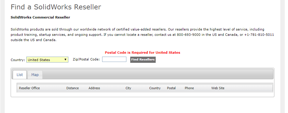
Figure 1: Vender Location
Many SolidWorks VARs are involved in the community as well. In some cases, they support and sponsor local SolidWorks user groups. They will also present at said user groups to teach tips and tricks within the software.
Your local VAR will help you determine the correct package of SolidWorks needed for you or your business. They may also suggest different add-ons that may increase your efficiency or help expand your capabilities.
To find a VAR in your area, follow the image below, fill in your zip code, and click the “Find Resellers” button:

If you cannot locate a re-seller within your area, contact SolidWorks at 800-693-9000, and they will provide you with the information needed to find the nearest reseller.
If you have any other questions about SolidWorks “VAR”, feel free to reach out to us and we will try and point you in the right direction!

The painstaking task of rearranging an office or a production plant only to realize that the layout wasn’t what you expected is something that happens way too often. That process is changing as technology advances. Now, companies are noticing the benefits of using virtual reality beforehand to place all the items before the actual move.
Previously seen mainly in the gaming industry, virtual reality is spreading to a more useful tool in a wide variety of industries. This being said, no one likes to do the same task twice. Why not take the virtual step to ensure complete satisfaction before moving things around?
Ultimately, viewing something like an office layout with virtual reality helps save time and limit frustration. Depending on which software is being used, there is the ability to measure item locations, move items around, take in-app screenshots, and markup items while in virtual reality. All these items combined allows everyone involved to add their opinions on what they think a layout should look like.
Safety is the main concern for many companies whether it’s in the day-to-day life or during something like a major move. In instances like a plant floor layout, there is a lot of room for error when there are multiple people and maybe a forklift moving a piece of machinery only to realize it all needs to be done again since the machine doesn’t fit in the desired location. It may not be as severe with something like an office layout, but there’s still potential for error and injuries. Virtual reality solves the issue when it comes to ensuring correct item locations before the move begins, and it’s completely safe! All that’s needed is a single person and with one hand, items can be moved over and over without the worry of injuries.

Figure 1: Reorganizing the Office
We at Perception Engineering have been able to use this technology to aid us in redesigning our own office layout! We created many different versions, 17 to be exact, to show us potential outcomes with items placed in a variety of locations.

Figure 2: Different Configured Office Layouts
Figure 3 demonstrates the current layout of items at our office. Our company is growing often so we were faced with the problem of fitting more people and more equipment in the office.

Figure 3: Current Office Layout
Luckily, through virtual reality, we were able to find the optimal set-up that satisfied both overall efficiencies and giving everyone enough space to be comfortable. The process was very smooth and easy since we had an overhead layout view after moving items around while in VR to get the best setup.

Figure 4: New Office Layout
Enough can’t be said when it comes to the benefits of using virtual reality. This is only one instance where it’s a far superior solution to a current issue. The ability to move items safely and accurately is a big topic when it comes to office and production plant layouts. Some people may be skeptical at first, but all that can really be said is try it! Who knows, more and more benefits can be realized as soon as the headset is worn.


On an average day, you move from task to task without even thinking about it. Usually this doesn’t cause much trouble; however, here at Perception Engineering, as much of the work we do is on time-based quotes, we meticulously keep track of time spent on any given task. This allows us to give customers an accurate view of how time was spent on their project and what they’re paying for. It also keeps us on track to get our work done in the most time efficient way possible. To do this, we use Toggl.

With Toggl, you can easily keep track of the three most important things for your records. What job the task was for, a brief description of what you were doing, and whether a given task is billable to the customer or not. This allows you to provide a summary of the time spent on a project, both billable and not billable, to the customer once a project is completed. Another important feature is that you can correct any mistakes after making the initial entry. This allows for a run through at the end of the project to make sure there are no errors for billable entries and no missing information, and the ability to fix these problems without losing the whole entry.

Figure 1: Sample Entries
Of course, those features are not the only advantages to using Toggl. The dashboard and reports features are also handy tools. With these, you can further break down and sift through tasks and the time taken to complete them. You can also break down projects into pre-defined tasks and assign these projects to clients, making it even easier to organize your time entries. Best of all, you can get started for free! Not only is there a 30-day free trial with any plan you like, you can keep a free account, for teams of up to five members, which allows you access to basic time tracking features.
That’s all for now! If you like the content or have questions, sign up for our email list to stay in the loop for solutions or weekly content.


You’re working on a project in SolidWorks when you realize you or a project partner has made some unwanted changes and saved over any previous versions. It happens to the best of us. Looks like you’ll have to spend extra time remodeling the part to get it back to the way you wanted, just to spend more time now modeling the changes you wanted to make in the first place. Not so fast. If you are working with SolidWorks Product Data Management (PDM), you are presented with multiple options to potentially avoid, or quickly fix problems like this.
To find the version history of a given file, first, locate it in your vault within your file browser. If you were not working out of the vault initially, unfortunately, you will not be able to go back to any previous versions by adding it after the changes were already made. If you need any help setting up your first vault, see my previous blog post, Intro to PDM, for a walkthrough. Once you have located your file, highlight it and select the “History” button.

Figure 1: Location of Version History
This should then open a page similar to the one shown in Figure 2.

Figure 2: Example of Version History Page
Once this is open, the next step is to determine which version you need to access. The first option to do this is to read through the comments. This can be helpful; however, it can also be unreliable. There is no guarantee that anyone put a comment on when changing an event. If there is a comment, there is no guarantee that it is accurate. If you find a comment that seems inaccurate, you can edit it as seen in Figure 3.

Figure 3: Editing Comments in Version History
Once you are done editing a comment, make sure to select update. The other option for determining what version you need is done using the “View” option. Highlight a part that you think has potential to be what you need, then select the “View” button on the upper toolbar.

Figure 4: Upper Toolbar
This will open an eDrawings preview window of the selected version of a part, with which you can pan, zoom, rotate, and take measurements to confirm roughly whether this is the version you desire.

Figure 5: eDrawing Preview Window
Once you have determined which version you would like to obtain, you are presented with three options. These options are “Get”, “Save”, and “Rollback”. They can be found in the upper toolbar, depicted in Figure 4.
By highlighting an event and clicking the get button, you will retrieve that version to the local cache. The changes and events made after that version will remain in the version history; however, when you go back to your file browser, the part will appear as the version that you selected.
By highlighting an event and selecting the save button, you are presented with the option to save a copy of a given version. You can save this both in and out of the vault.
By highlighting an event and selecting the rollback button, you will delete all the events that occurred following the event highlighted. If you attempt to rollback an assembly, you will be presented with the window shown in Figure 6.
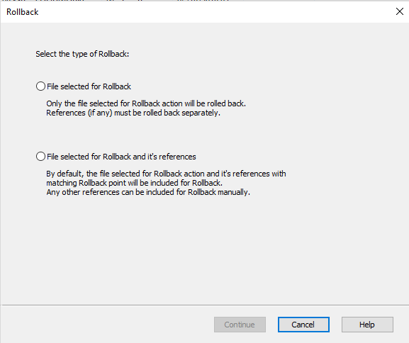
Figure 6: Individual or Reference Included Rollback
Once you have made your selection or are attempting to rollback a part, you will be presented with the window shown in Figure 7.

Figure 7: Rollback Window
Once you have entered your comments and you attempt to continue you will be presented with one final confirmation, making sure you know that all versions after the selected event will be permanently deleted. Check the selection that you understand and confirm the rollback.
Note: If you are working with various projects in different versions of SolidWorks this feature can be especially useful. If you accidentally save a project from an earlier version of SolidWorks to a more recent version, you can rollback to revert it back to a file type that works with whichever earlier version of SolidWorks it is you are working with.
That’s all for now! You now know how to navigate the version history provided in SolidWorks PDM. If you like the content or have questions, signup for our email list to stay in the loop for solutions or weekly content.


Have you come across an issue with SolidWorks Visualize where the exact desired appearance isn’t available in their wide variety of selections? Nothing is more satisfying than having what you imagine appear exactly as though in a final render. This blog will help to create inform readers on how to achieve these appearances!
In Visualize, appearances are the items that are applied to imported files or any models that are created in the software to aid them in appearing realistic. There is a large number of appearances already supplied by SolidWorks from the different type of wood finishes and metals to the more unique ones such as grass and soap bubbles. SolidWorks provides standard appearances that are saved when the software is installed, and they also have a cloud-based section that provides more custom appearances.
With SolidWorks Visualize Standard 2018, there are 15 different types of appearances that the user can create when creating their own. The correct selection will need to be chosen when deciding which is most applicable for the component it’s being applied to. This is fairly crucial because each of these will have a few to several different options for customizing the appearance. Some of these are simple such as the base color to more advanced like the density, roughness, and scattering of the color.

Figure 1: Examples of Appearance Options
Since there are so many different options for creating appearances, for this blog we will be focusing on creating a generic appearance. To create a new appearance, first, navigate to the appearance tab, right-click within the window, and select New Appearance.

Figure 2: Creating a New Appearance
Next, select the drop-down arrow to Appearance Type and select the Generic option.

Figure 3: Selecting Generic Appearance
Compared to some of the other different appearance types, generic has many different customizing options. Below, is a brief explanation on each of these options.

Figure 4: Options in Generic Appearances
For creating custom colors that SolidWorks doesn’t provide in either the local library or cloud library, it’s best to get into the software and create your own. It can take some time to dial in exactly what each option does and what they’re capable of, but it becomes second nature with practice. These custom created appearances can be saved and then used on any future projects!


SolidWorks Visualize is a great software for creating realistic renderings of any company’s products quickly. The software is also able to import 20+ different file types from any SolidWorks parts and assemblies to STEP and STL files. This blog will mainly focus on importing options for SolidWorks parts and assemblies.
Like most softwares, it’s simple to create and start a new project. Files can either be dragged straight in from something like a file explorer or directly from a downloaded web browser. The other way, which takes a couple of extra steps can be done just as easily. First a new project will need to be created and that’s completed by selecting the New Project button when first opening the software.

Figure 1: Starting a New Project
The next step is to select File from the main toolbar. Finally, select Import and locate the file you wish to render in Visualize.

Figure 2: File and Import
Being that there is a wide variety of different file types that can be imported into Visualize, the specific import options will need to be catered to the file type. For instance, we would want to choose different import options between something like a 3D PDF and a regular SolidWorks part file. Below is a list of the different import options and a little information on each. The main thing to take away from this is that these options will determine which colors, appearances, and textures will carry over from the original files and it will determine how added colors from Visualize will appear whether it’ll attach to the entire part or just the surface.
Automatic – uses the best combination amongst all the import options to mimic the way the product is assembled in real life (Typically works well for all SolidWorks files).
Flatten – ignores all grouping and imports a single part. Component appearances can still be added to individual components without adding to the entire assembly.
Group/Appearance – more aimed towards Autodesk Alias .wire files as it retains the group hierarchy within the file, subdividing or subgrouping items based on the appearance, color, and group that is assigned.
Layer – imports based on which surfaces are assigned to layers within the CAD package, ignoring any appearance or color assigned. All surfaces assigned to each layer in the CAD file are imported as a single part.
Layer/Appearance – favors layers first, then appearance second to divide the model into parts.
Appearance – imports surfaces based on which are assigned the same color/appearance within the CAD package, ignoring any grouping or layering. All surfaces with the same color or appearance will be joined into a single part for quicker model painting.
Appearance/Layer – favors appearance first, then layers second to divide the model into parts.
Retain Structure – retains the raw hierarchy of the assembly model that is in the CAD package. This could yield many parts which will directly affect performance.

Figure 3: Import Settings
Not enough can be said at how great SolidWorks Visualize is as far as creating photo realistic photos and its ability to allow for many different file types to be imported. Always remember that when importing any file to double check the part grouping. This will be the main factor at determining how appearances and textures will be applied to the imported data!

