What’s New to SolidWorks 2019

What’s New to SolidWorks 2019

With another year coming to a close a new and improved version of SolidWorks has been released, SolidWorks 2019. This new SolidWorks version is full of powerful new modeling tools and various other updates to help bring design and manufacturing closer together. These updates and features cover all aspects of SolidWorks including, Assemblies, Routing, Drawings, PDM, Plastics, Simulation, Visualize, and much more.

Figure 1 – Photo from SolidWorks Event

Updates to Assemblies, Parts, and Drawing Features

 Making large assemblies both run and load faster has been a goal of Dassault’s almost every year. With assemblies growing more and more complex the need for better assembly performance is long overdue. SolidWorks 2019 has done a great deal to fix this issue by taking computing stress off the CPU and sharing it with the computer’s graphics card. This allows for quick and seamless assembly manipulation. 3D textures can now be applied to 3D models. This process used to take many features and a large chunk of time to add in a simple feature like knurling. Now all the is needed is textural appearance and the use of the new “3D Texture” tool to create complex surface geometries quickly and easily. As for drawings, SolidWorks 2019 allows cell border thicknesses to be changed individually for each cell. Opening drawing documents also will now prompt a progress indication to show both number of components and time taken to open the document.

Updates to SolidWorks Visualize

 Setting up a render to achieve picture perfect accuracy can take a long time, and even longer if your session ends unexpectedly and all that work needs to be redone. SolidWorks 2019 offers a new auto-recover option inside visualize to help prevent lost work if the session is closed unexpectedly. Along with the auto-recovery features comes the denoiser option to visualize to help produce faster and more accurate renders. The denoiser is a simple checkbox option to be selected, it allows for fewer passes and faster render time using a post processing technique to filter out unfinished images. 

 Updates to SolidWorks Plastics

 As for plastic part and mold creation some changes do come in 2019 as well. With the new SolidWorks version comes the ability to add geometry based boundary conditions to models. This update allows for features on the model to be assigned as injection locations, control valve locations, and temperature boundary conditions. An enhanced algorithm has been added to allow more accurate and complicated cooling channels to be formed from sketch lines. This new algorithm gives cooling channels an overall better look and greater precision. Mesh enhancements have also been made to SolidWorks plastics. SolidWorks 2019 allows a mesh to be created before a part file has been saved off. Mesh can also be assigned faces, edges, and vertices before creation. Information about the mesh statistics can now also be pulled in 2019 allowing you to view any bad elements about the mesh and much more.

Updates to SolidWorks Routing

 SolidWorks routing has now been updated to allow the creation of partial or fixed length coverings. A “fixed length covering” tool has been added in to allow various locations and segments of the routing to have custom covers. Improvements have also been made to the Routing Library Manager. These updates to the library include displaying only essential tabs that are needed for routing creation, along with increased response speeds when switching through tabs.

Updates to SolidWorks PDM

 This new version of SolidWorks comes with a long list of much needed updates to PDM. First, performance has been improved for handling large assemblies and complex reference structures. This allows for assemblies with a large number of components to be checked in quickly and easily. Conditional notifications have been added to allow predefined conditions to be set and send transition notifications to users and groups. This also allows notifications to be sent dynamically to users based on variables found on the data cards.

Conclusion

 SolidWorks 2019 is bringing a multitude of updates and features to help users bridge the gap between design and manufacturing. It does not seem like it will be long before every tool you need to go from design to manufacture will be available to you in a single program. What was talked about in this blog was only the beginning to some of the updates in SolidWorks 2019. If you would like to dive deeper into some of these new updates or find others that were not talked about visit the SolidWorks site here: http://help.solidworks.com/2019/English/WhatsNew/c_welcome_solidworks_2019.htm?id=9e4cebd3c875458d9bcb529e16b720ab#Pg0

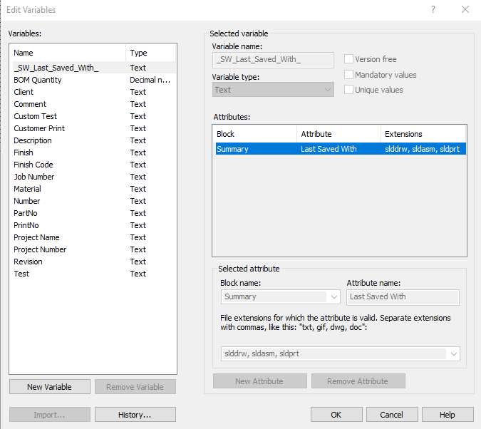
Figure 2 – Photo from SolidWorks Event 2

Written By:

SolidWorks: CAM Tool Path

SolidWorks CAM

SolidWorks CAM is a fully integrated, knowledge-based technology that allows you to integrate design and manufacturing processes under one system to evaluate designs earlier in the process to avoid unexpected costs and delays in finishing products on time.

What is SolidWorks CAM?

SolidWorks CAM provides CNC programming right inside SolidWorks. This program generates all the machining information needed to create components quickly with it’s feature recognition abilities and with added SOPs (standard operating procedures). These SOPs can be input manually and saved to match the company’s standards based on their best practices with things such as tool types and sizes. The best part of all of this is that SolidWorks CAM Standard is free with any SolidWorks 2018 subscription! There is some extra cost to using the next step up with some added features inside of SolidWorks CAM Professional.

Advantages

One large advantage with using this add-in is that it’s built right into the SolidWorks interface. All that will need to be done in order to access this tool is to enable it by going to the options gear at the top of the screen while in SolidWorks, selecting the drop-down arrow and selecting add-ins.


Figure 1: Add-ins Tab Within Options

In this window, the next step is to navigate to the SolidWorks CAM option and choose to activate it. The option to have it load on startup can also be selected if they want to use it without having to go through this window each time to enable it.

Figure 2: Enabling SolidWorks CAM Window

Another advantage with SolidWorks CAM is its use of knowledge-based machining as well as the tolerance-based machining. The option to extract machinable features is very useful when it comes to creating toolpaths. The software will automatically recognize features and based on both tolerances and the company’s SOPs, provide the toolpath in no time! The software also allows for going back through and adjusting the created toolpaths to ensure the best times possible for creating parts. For instance, the time it took to create the toolpath for the designed component in Figure 3 took less than 2 minutes to generate.

Figure 3: Toolpath Timed Part

Finally, there is no worries associated with adjusting component features and potentially ruining the created toolpath. SolidWorks CAM has the ability to instantly adapt and change creating new cutter paths and machining operations for the edited feature. Not only will it adjust to allow for new features to be created, but it will also warn the user if there is a potential of collision between the stock and the tool shank or holder. Processes can the be moved to help avoid this issue whether it’s adjusting which tool cuts when or changing cutters.

Figure 4: Simulated Toolpath

How it’s Used

There are many ways that this software can be used to benefit a company. For one, it can be used to ensure that designed parts are able to be manufactured with no issues. Before parts are sent to the shop floor to be created, the tool path can be monitored and inspected for problems with features not being able to be machined. This is big for eliminating any question on if the part can actually be created.

It can also help with saving time on machined parts. After the software extracts the machinable features, it will generate the operation plan for the features, generate the toolpath, and finally, it will simulate the toolpath. Once this has been created, the simulation can be inspected to see if there are time-saving opportunities for using one tool as opposed to another or if there are too many tool changes between creating features. With this software, operations can be manually adjusted and reorganized based on the most optimal way to produce parts accurately and quickly.

Conclusion

SolidWorks CAM is a great software for all of the things it can accomplish and the fact that it’s free with any SolidWorks subscription is just an added bonus! With all of the capabilities and customization it has, it’s definitely something to look into for companies that work with CNC machines, tool pathing, or just generating G-code for a customer.

Written By: 

SolidWorks: Forming Tools

SolidWorks: Forming Tools

Over the years at Perception Engineering, I have modeled and detailed hundreds of sheet metal parts. Often these sheet metal parts will require specific tooling to match the customer specs. Taking to the internet for help on creating tooling yielded minimal results. Having to do my own research to ensure the customers receive the quality parts they requested; I’ve decided to post my finding to help others out.

Tooling Profiles

SolidWorks has included an assortment of default forming tools for sheet metal parts in the design library. Located on the left side of the SolidWorks interface, click on the Design Library dropdown to access the default forming tools.


Figure 1: Design Library

The forming tools can be applied to any sheet metal part by dragging the desired tool on the sheet metal part. For this, I chose the lance & form shovel. This feature can then be fully defined after the tool is dropped on the part.

Figure 2: Forming Tools

The form tooling feature tree will open by default to move the tooling to the correct location. Most tooling positions can be easily adjusted by simply defining the center and rotation angle. If needed the tooling can be flipped too.

Figure 3: Tooling Feature Manager

In the Position tab shown in the figure above, the tooling can be fully defined and the option to add more tooling features can be done if more sketch points are added to the sheet metal part.

Figure 4: Defining Tooling

Figure 5: Tooling

Custom Tooling

At times other customers will require custom tooling. If the customer provid their custom tooling then simply drag and drop as shown above. However, most of the time Perception Engineering must make the tooling to match the customer profile. To do this, open a new part file.

Create a rectangle extrusion large enough to fit the tooling desired, this rectangle extrusion will later be deleted so don’t spend too much time with getting a perfect size.

Figure 6: Custom Tooling Base

Now the custom tooling can be created as you would any other part: lofts, sweeps, extrusions, and fillets to create the customer stamping profile. Be sure that any radii on top of the tooling is smaller than the material thickness otherwise SolidWorks will not stamp the sheet metal. 

Figure 7: Modeling Tooling

The Form Tool can be found in one of two places: search Form Tool in the command search or by going to insert then sheet metal. 

Tooling Profiles

Figure 8: Forming Tool

The Form Tool Feature tree will pop-up and prompt you to select the stopping face. This will ensure the tooling will press up to the desired face forming the sheet metal as specified. Faces to remove will punch holes in the sheet metal with each face selected.

Once all the faces have been specified, the Insertion Point will need to be identified. This point similar to figure 4 will define the tooling within the sheet metal part.

The model can then be saved as a Form Tool File. Select File Save as and find Form Tool (*.sldftp) and be sure to save the file to the design library forming tools folder similar to the default tooling used ealier. 

Figure 9: File Save as

The tooling is now successfully created! Go back to the sheet metal part that needs the tooling and find the tool. Place it on the sheet metal part and define the tooling location as you read above.

Figure 10: Custom Forming Tool

If you have any question, please feel free to contact me via LinkedIn. Thanks for reading the blog!

Written By: 

SolidWorks: Custom Drawing Template

Custom Drawing Template

A drawing template is one of the main components to any assembly or part drawing. A drawing template allows you to convey all information about a part or assembly in a clean and organized manner. The key features of a drawing template are simplicity and clarity. This blog will demonstrate how to make a simple custom drawing template in SolidWorks! 

Opening A Drawing Sheet

To create a custom drawing template, a blank template is needed to start the creation. SolidWorks offers multiple different sizes and shapes of pre-made drawing templates inside the programs files. One of these pre-made templates will be open and altered to make it blank.  Click on the new document command on the toolbar at the top of the screen or under the file drop-down menu. After trying to open a new file, a pop-up box will appear. Under the novice setting tab, there will be three options: start a part, assembly, or a drawing. Choose the create new drawing option. Another pop-up window will appear with a list of A-E drawing templates. These are SolidWorks default templates. Any size can be chosen but for this blog, the A(ANSI) Landscape template will be modified. An image of how to get to the custom SolidWorks templates is shown below in Figure 1.


Figure 1: SolidWorks custom template location

Clearing the Format

Once the pre-made template has been opened, the formatting needs to be cleared to be able to input a new custom template. In the feature manager on the left, there will be two features, these are “Annotations”, and “Sheet1”. Click the drop-down arrow next to sheet1 and another feature will appear called Sheet Format1. Right click on Sheet Format1 and select delete, the drawing template will then turn blank. An image of how to clear the format is shown in Figure 2.

Figure 2: Clearing the sheet format

Editing the new sheet

Now that the sheet has been cleared, a new format can be created on it. In the drawing, select the Sheet Format tab located on the toolbar near the top of the screen. Select the Edit Sheet Format command on this tool tab. After this command is selected the other two commands on this tab will become available to use. Now, select the Automatic Border command. Where to find these commands is shown in Figure 3.

Figure 3: Editing commands location

After the Automatic Border command is selected, the property manager will show a delete list selection box. Since the format is already cleared, this step is not needed. The blue arrow at the top right of the property manager can be clicked to move onto the next step in the command. After the blue arrow is clicked, the property manager will be filled with multiple different options on how to adjust the border that is being previewed on the drawing sheet. The zones, margins, line size, and borders can all be edited here. Once the desired sizes have been chosen, click the green check mark at the top of the property manager. There will now be a border around the drawing template. The Automatic Border property manager is shown in Figure 4.

Figure 4: Automatic Border property manager

Adding Sections

Now that the border is finished, some sections for information need to be added to help keep the template organized. To add in sections, they simply need to be sketched in. Go over to the sketch tab and select the line or rectangle command. Create some boxes and proportion them to the size and shape that is desired for the custom template. An example of the sections made for this blog is shown in Figure 5.

Figure 5: Example added sections

After the sections have been added in they need to be labeled. This can be done by placing annotations notes in each box. The Note command can be found under the annotation tab on the toolbar near the top of the screen. A note is placed in each box of the title block. This is done to give an input location for information about the drawing. Note size and shape can be adjusted by double-clicking on the note itself. An example of the layout for notes in a drawing template is shown in Figure 6 below.

Figure 6: Example section labels

Finishing Touches

Notice that there is still a large empty space inside title block area. Typically, in this space or one like it, a decal belonging to either the person or the company is placed to show ownership of the template. These pictures also help make the template look more aesthetically pleasing. For this blog example, the Perception Engineering logo will be added. To add a picture to the template the edit sheet format command must still be activated. If it is not, click on the command again. Go to tool on the toolbar at the very top of the screen and drop down the menu. Find the sketch tools menu and hit that drop-down menu as well. Under the sketch tools menu, there will be a sketch picture command. After clicking this command simply select the desired picture from its file locations and it will be placed onto the template. The picture can then be sized and edited in its property manager on the left-hand side. An example of this is shown in Figure 7.

Figure 7: Sketch picture example

Saving the New Template

Now that the new drawing template is complete, it must be saved! To save this as a template to be used all that is needed is to save the file as a drawing template (*.drwdot) file. After it has been saved as a drawing, the file locations need to be edited to pull the template. Click on the gear at the top of the screen and select file locations in the menu on the left side of the pop-up menu. Under the “show folder for” drop-down menu, select Document Templates. All that is left to do is select the folder that the drawing template was saved in and it can now be pulled to use as a template anytime! How to access the file locations is shown in Figure 8.

Figure 8: Editing the file locations

Final Thoughts

The purpose of a drawing template is to help with organization and presentation of a drawing and its information. A well-organized drawing template is a sure-fire way to portray professionalism when creating drawings. Even with just a simple template and title block such as the one shown in this blog, the look of a drawing can be increased as well as how easy it is to read and gather information.

Written By:

Comparing CAD Software Solutions

Comparing CAD Software

Here at Perception Engineering, we work with to various companies across many industries in the West Michigan area. Among these companies, many different CAD softwares are utilized. Although SolidWorks is the most widely used, we have assisted customers using other softwares such as Inventor and Fusion 360. With so many different CAD options out there, it may be difficult to decide what is the right fit for you or your company. Whether you’re a well-established company or an Inventor simply trying to dream up a design, selecting a 3D modeling software is an important decision that requires much research and examination. This blog will break down a broad range of popular softwares and briefly list some pros and cons as well as their researched costs. It is important to note that many CAD programs fall within specific tiers based on how they are utilized and needed in industry (low-middle-high). The softwares covered in this blog are listed based on the tier they fall in and the pros and cons were best developed and researched relative to their tier.

Thank you for reading! If you have any questions or comments feel free to contact me. Be sure to sign up for our weekly email list. 

Written By:

Virtual Reality: Softwares

Virtual Reality Softwares

With virtual reality technology is growing and growing, there are a wide variety of softwares that can suit a company’s specific needs. Finding the right one for the company is all up to trying different softwares to find that exact fit! At Perception Engineering, we’ve been actively testing different softwares and this blog will cover some that we’ve been using.

Prospect


Although Prospect is mainly used in building industries, we have been able to test some of our large assemblies and have faced no issues. This software has been created by the IrisVR company. It has many useful features and some overall cool things you can do to manipulate imported models. There are many different pricing options starting with the Basic version for $50 per user/month up to $350 per workstation/month. With each tier, more options and functions are unlocked.

Figure 1: Prospect Interface

A few features we’ve tested have been their measuring tool, the markup tool, and the ability to section models. The measuring tool is easy to use, and it gives the distance from one surface to the next in a single button click.

Figure 2: Measuring in Prospect

With the markup tool, the user can draw directly on components to be reviewed later. They also have a camera tool to capture the markups!

Figure 3: Markup with Prospect

The last tool in this blog that we’ve enjoyed using is the live sectioning option. Any point in the model can be sectioned by just moving the controller over the area.

Figure 4: Sectioning with Prospect

We haven’t had any issues while using this software. Perception Engineering uses SolidWorks to create components and the only easy file format we can produce to load in Prospect is a .obj or .fbx file. This adds a couple of steps, but this most likely isn’t an issue for companies in the building industry that use design software like Revit or SketchUp.

For more information, visit their website: https://irisvr.com/prospect

Unreal Engine 4

Known mainly for its work in the gaming industry; Unreal Engine 4 has been a software we have been spending some time with viewing models. The company responsible for this software is Epic Games. As previously mentioned, they’re mainly known for their work in the gaming industry, but they have been making noise in the engineering world. This is a free software to download and use, but it does require an account!

One thing using this software that we liked was the ability to add simulate physics to components. Other software we’ve used, once you let go of an item, it floats in space and stays in the exact position. With Unreal Engine 4, when an item is released, it will simulate what would happen if it was held and released in the real world.

Figure 5: Physics in Unreal Engine 4

One issue that we’ve run into while using this software is the amount of work and time it takes between starting the project and the end goal as far as being able to take assemblies apart. With time, this process could be sped up, but it can be tricky starting out.

For more information, visit their website: https://www.unrealengine.com/en-US/blog

Demo3DVR for SolidWorks

Demo3DVR is the main software we’ve been using at Perception Engineering. The company who produces this software, Emulate3D, is a certified solution partner with SolidWorks. Overall, we have been very satisfied with the capabilities of the program, the speed and helpfulness of their customer support, and changes they’ve been making with the software. One aspect we like specifically about this software is its integration with SolidWorks. it is an add-in to SolidWorks so loading files into virtual reality is a click away. Per license, Demo3DVR for SolidWorks is a one-time fee of $995.

Figure 6: Emulate3D Logo

Once in the software, there is a wide variety of things the user can do with the software. One item is being able to take assemblies apart piece by piece to see all the components that make it up. This has been useful for checking for interferences, ensuring correct component sizes, and checking for correct component locations.

Figure 7: Warehouse Machine Clearance

They also have a mobile app for viewing files either with a mobile headset, Google Cardboard, etc., or models can be viewed and spun around by hand. This can also be viewed on tablets and downloaded from either the Google Play Store or the iOS App Store. It’s a free app that doesn’t require an account to view files.

For more information, visit their website: https://www.demo3d.com/demo3dvr-solidworks/

Conclusion

In conclusion, there are many virtual reality softwares in the world today. It’s all about finding which one(s) will fit the companies needs and meet their requirements. It may be a trial and error process at first, but with time the most fitting software will be found based on the needs of the company!

Written By:

SolidWorks: PDM Data Cards

Keeping track of part properties in SolidWorks can be a very tedious task. If multiple properties need to be changed from part to part on a project, it can cut into your productivity, taking time away from further refining your design. Luckily, with SolidWorks Product Data Management, we can remove much of this wasted time with the use of data cards.

Data Cards

Data cards are a feature on SolidWorks PDM that are linked to the data contained in the SolidWorks properties of a part, assembly, or drawing. With these, you can view, and even edit a file’s properties directly from the file browser. They also allow you to search through your design files using properties as search constraints. There is a default data card that is included when you create your vault. It is shown in Figure 1.


Figure 1: Standard Data Card

If this will suffice, then all you must do is add the file extension. Go to the Administration application and under the Cards drop-down in your vault, double-click on Quick Start Data Card. Once the card editor opens, fill in the file extensions you would like it to be applied to under Card Properties, on the right, then save the card in your vault. The extensions can also be filled in while saving. Do not use a period in front of the extensions. In addition, separate each extension by a semi-colon (i.e. sldprt;slddrw;sldasm). If you would like to include the usage for part, assembly, and drawing files, you can copy and paste the previous example. You can omit any of these to serve your purpose if you do not want it applied to all three file types. Your data card is now ready to use. One way of using it comes with saving a new file to your vault. As you attempt to save a new file in your vault, your data card will show up as shown in Figure 2.

Figure 2: Data Card Save Prompt

This popup window will allow you to enter the properties found on the data card for your file. Another way to use the data card is within the file browser. First, navigate within your file browser to find your vault. Once in your vault, highlight the file you would like to edit the properties of and make sure it is checked out before you proceed. Then select the data card tab and you can view and edit your properties right from within this window.

Figure 3: Data Card in File Browser

As you can see in Figure 3, this is not the default data card. If you would like a more customized card, with specified properties you must create your own. To do this, open the Administration application. Then, right-click on File Cards and select New Card… which will open the card editor.

Figure 4: Adding a New Card

Within the card editor, you can add things to your card such as frames, edit boxes, tabs, radio buttons, checkboxes, etc. These can all be found in your toolbox along the top of your card editor page. It should look like Figure 5. You can hover your pointer over any of these selections and a description should appear.

Figure 5: Card Editor Toolbox

Edit boxes are the most useful for properties, as they are linked to properties and can be typed in manually to the user’s preference. To insert an edit box, select the edit box tool and click and drag on your card to whatever size you prefer. Next, you must link it to a property. Whatever you enter in this box is what will show up within your properties on SolidWorks. To do this, select an option from the drop-down variable name drop-down, as shown in Figure 6.

Figure 6: Variable Selection

If there is a variable that you do not see in the list or would like to link an edit-box to a pre-existing variable within your SolidWorks properties, you’ll have to create a new one. Select the button labeled “Variables…”, located under the drop-down menu. This will open the window shown in Figure 7.

Figure 7: Variable Editor

Select New Variable and enter whatever you would like to name the variable in Variable name, then select New Attribute. If you are trying to link a box to a pre-existing property, this step is especially important. Select CustomProperty from the Block name drop-down and then enter whatever you would like the property to be called into Attribute name. If you are trying to link this to a pre-existing property, the attribute name must be the same as the property name that is found in the SolidWorks properties, capitals, spaces, punctuation, everything. Enter as many text boxes as you need for your properties and label them with the Static Text tool and there you have it, all you need for a basic but fully functional data card.

That’s all for now! You now know how to create and use your own SolidWorks PDM data card. If you like the content or have questions, signup for our email list to stay in the loop for solutions or weekly content.

Written By: 

SolidWorks: Property Tab Builder

SolidWorks: Property Tab Builder

In this blog, we will be discussing the SolidWorks Property Tab Builder. The property tab builder allows the user to build preset properties that can be loaded into parts and assemblies. We will also look at how to integrate these into the SolidWorks Properties Tab, and some of the convenient ways to use the SolidWorks Properties Tab.

Property Tab Builder

To locate the Property Tab Builder, click on the Start Menu, scroll down until you find the folder called SolidWorks 2018 Tools, expand that folder and select the Property Tab Builder 2018.


Figure 1: Start Menu

Once the application is open, it should look like so:

Figure 2: Property Tab Builder

On the left-hand side of the window are the various elements that can be used to enter part property attributes. We break these down into further detail below. To add an element to the customer properties tab, click and drag the element into the Custom Properties column. Throughout this blog, we will be showing examples of how certain elements can be used in the workforce.

Groupbox

A groupbox is a feature that allows the user to group elements together within the Custom Properties and create sub-headings by dragging the elements into the desired groupbox area.

Figure 3: Groupbox

Textbox

The textbox field is used if you wish for the user to type in a value.

Figure 4: Textbox

The caption is what will appear as the title of the data entry box within the Customer Properties Tab. The name of the custom property attribute is what the inserted text will be assigned to within the part. The value is what the customer will be inputting when filling out the customer properties.

In this example, we will be using the textbox field to enter a part number the user wishes to assign to the part, as shown in the image below.

Figure 5: Textbox Information

List

The list element can be used to create a drop-down list for the user to select from a variety of values.

Figure 6: List

One example of how to use the list element is by having the user select what category the component can fall under. In this case, the user has the option to select Manufactured, Purchased, or Fastener.

Figure 7: List Properties

Number

A number element is a useful tool for a user to increase or decrease a numerical counter for the desired attribute.

Figure 8: Number

One example of using the number element is by creating a counter for the desired quantity of a part to be manufactured, whether there are more than one in an assembly or a replacement part is desired. The image below shows the use of using the number element for BOM quantities.

Figure 9: Number Properties

Checkbox

Another custom property element that can be used is the checkbox.

Figure 10: Checkbox

An example of the checkbox is using it as a Yes or No indicator. In this case, we are using it as an indicator for the user to identify whether the component is constructed out of sheet metal or not.

Figure 11: Checkbox Properties

Radio Button

The radio button element is very similar to that of the checkbox, but it can allow the user to select from a variety of variables.

Figure 12: Radio Button

A popular practice in the sheet metal industry is to indicate the surface class of a part. We used different surface classes as the variables for the radio button element as shown below.

Figure 13: Radio Button Properties

Once all the elements and attributes you wish to include have been added to the custom properties, save the file to your desired location. You can save the file as a part, assembly, drawing, or weldment custom property file by changing the type under the Control Attributes column.

Figure 14: Property Types

SolidWorks Property Tab

If you open a new part using the templates provided by SolidWorks, the part properties should be blank like so:

Figure 15: Blank Part Properties

Now go through and link the file location of the custom property files to the location where you save the custom part property file. Once that is completed, go to the Custom Properties Tab on the right-hand side of the screen. You should see the part properties we created in the property tab builder.

Figure 16: Custom Properties Tab

Now fill out the elements within the tab as shown below and click apply.

Figure 17: Custom Properties Tab Information

If we go back to our part properties, they should include all the information we added to the custom properties tab.

Figure 18: Part Properties Populated

The custom property files are a great tool for implementing part properties into STEP files that you have downloaded, or even for updating the properties of a file that might be out of date. This is a more efficient method than copying part properties from one file to another.

That’s all for now! You now know the basics to create a custom property file. If you like the content or have questions, signup for our email list to stay in the loop for solutions or weekly content. Cheers!

Written By:

Augmented Reality eDrawings

Augmented Reality with eDrawings

Imagine being able to take a CAD model from SolidWorks and view it on a mobile device in real time with real objects. What seemed to be impossible is quite real and easy to do!

What is Augmented Reality

Augmented reality, or AR, is technology that uses a computer-generated image in combination with the users view in the real world creating an item that can be seen next to real items. A couple of well-known apps that have brought this technology to the mainstream have been Pokémon Go and Snapchat. Both apps have been able to take their created content and allow the user to view them in day to day life with the users given surroundings.

Software

The software we have been using at Perception Engineering to view our created CAD models is eDrawings. This app is available for download in both the iOS app store and the Google Play store, however, the AR will only work for iOS currently. There are two different version: eDrawings for $1.99 and eDrawings Pro for $9.99. From what I’ve seen reading and learning about these softwares, there isn’t much of a difference, on the AR side at least, between the two. One thing that the Pro version can do is allow the user to view cross sections of the imported models inside and outside of the AR mode.  


Figure 1: eDrawings Apps

Setting up Files and Using the Software

We will be mainly be going through the step-by-step process of taking a SolidWorks part/assembly file and opening it in AR with the eDrawings app. The steps for importing an EASM or STEP will be very similar with the only difference being the file types.

The first step is to get the file to view in AR on your tablet or mobile device. This is accomplished by emailing the files to the device.

Figure 2: Emailing Part File

These files can either be downloaded and saved to the phone or they can be opened directly into the eDrawings app. For this example, we won’t download and save the file.

Figure 3: Opening Window

When selected to “Copy to eDrawings”, it will open the file directly into the eDrawings app!

Figure 4: Part in eDrawings App

Once the file is on the tablet or mobile device, the next step is to acquire the QR code and print it. This is done using the app by opening the part in the app, selecting AR from the menu, and choosing the “Get Marker” option. This will open the QR code and prompt the user to input an email address. This QR code is not unique from part to part, the software determines which file to show in AR based on which part is open in the app.

Figure 5: QR Code

Now it’s as simple as pointing the QR code on the screen to the printed off code. The model can be spun around using one finger and panned on the screen using two fingers. The model will also come in with a 1:1 scale based on the size of the QR code.

Figure 6: Viewing Model in AR

Tips and Tricks

There are a couple of little tips and tricks with using this software that can aid in having an overall better experience. The first one is manipulating some of the components inserted if they’re in an assembly. This software allows the ability to either hide or make the component transparent if a better, clearer view is desired. This is done by selecting the pop-out manager highlighted in Figure 7. At the bottom right corner of the screen are to make selected components either hidden/shown or solid/transparent. Simply select which option to apply and then select the component for an instant update. Components can either be selected in the feature tree flyout or on the assembly.

Figure 7: Hide/Show and Transparent/Solid Options

The next tip is cleaning up the user interface for a better view of the augmented model. The app can appear cluttered at first but simplifying and hiding all the options is a click away. Highlighted in Figure 8, simply select this expand/compress option and all the information will be hidden except the model and the option to bring back the information.

Figure 8: Simplified Interface

Issues

With this technology still being new, there are still some bugs and issues that will become more and more noticeable while using the software. One issue that will become obvious is the file size can’t be too large. If it ends up being too large, there will be a lot of stutter points when trying to rotate or pan the model. There is also the possibility of the app crashing because it can’t handle all the data/information being imported. This can be adjusted some by either defeaturing the components or removing some of the unnecessary components. Unnecessary components to the overall structure being things like nuts and bolts.

One other issue is the model when it’s inserted being too large. Some tests were done changing the size of the QR code, but some items still came in too massive to where it was impossible to see any portion. The only solution to this has been trying to adjust the scale immediately after locating the QR code. That is done by selecting the option under the AR button (highlighted in Figure 9) and manually typing in the scaled percent to try and fit in the view.

Figure 9: Scaling Option

Conclusion

In summation, this a fun and useful app to have! We here at Perception Engineering have been taking some of the different models we’ve worked on in the past and viewing them with this eDrawings app. Though it may seem limited in what we can do with this app, it’s only the beginning of the changes coming with new technology.

Written By:

SolidWorks: Part Configurations

Part Configurations

Often customers will want to view multiple configurations of the same part to see which they like best. Instead of creating four or five new part files to show the customer, it is much easier to create each version of the same part with the configurations manager tab.

Configurations

Within the configurations tab on the feature manager tree, right click on the Part and select Add Configuration.


Figure 1: Configuration tab location

Organize Configurations

Each configuration should have its own unique name to quickly distinguish between each configuration. This will help distinguish each configuration within assemblies and drawings to ensure the correct model is chosen.

Figure 2: Configuration Name

The saved configurations will appear in a pop-down menu within assemblies and drawings as seen below. Simply click on the part and the option to choose between each configuration will appear. Keeping simple and descriptive names will be the best option for configuration models.

Figure 3: Pop-down Menu

Modifications to Configurations

The feature tree model gives the option to suppress and unsuppressed features. Each configuration will be slightly different which means some features will need to be suppressed and others unsuppressed depending on the design intent. The default configuration should be the original design before modifications are incorporated.

Default:

Figure 4: Default Bracket

Large Mount:

Figure 5: Large Bracket

Small Mount:

Figure 6: Small Bracket

The reason each configuration has its own hole wizard feature is to ensure it has no relation to any other configurations. If bracket were to have only one clearance hole, then all three configurations will be identical; hence the need for three separate hole clearances.

Stay up to Date

Thanks for reading our blogs, if you enjoy the content please subscribe to our weekly blog postings. Perception Engineering stays up to date with the latest technologies and techniques and is happy to help answer any questions you may have.

Written By: