SolidWorks: Basic Hole Wizard

The proper formating of the hole wizard feature will allow the user to easily control and change any number of holes at once. This is good practice for the modeling efficiency will be much faster and in the future, adding fasteners will be much smoother as the hole wizard can be used to pattern features.

Hole Wizard Introduction

Hole wizard is a useful tool in SolidWorks used to control the features and properties of multiple holes at once. The Hole Wizard Feature allows you to create a variety of different types of hole cutouts for area and function specific applications.

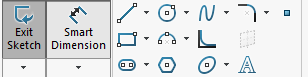
Figure 1: Command Manager Icon

The hole option types are as follows: counterbore, countersink, drill, straight tapped, tapered tap and legacy. Among each of those options, Hole Wizard also allows you to generate counterbore, countersink, and traditional slots. The counterbored and countersink holes add a flat-bottomed hole cut and angled lead on the top side of the hole which is often used to sit fasteners flush with the surface of the part.

The drilled hole type allows access to various drill sizes and varieties, such as a dowel, fractional, helicoil, number/letter sizing, screw clearances, and finally regular or pipe tapped drills. Straight tapped holes add a constant threading along the hole direction; while tapered tapped holes add the varying hole and thread size with respect to the hole depth. Finally, the legacy hole is customizable hole feature that allows you to input various sizing to construct a hole specific to your needs.

Operating the Hole Wizard

First selecting the Hole Wizard icon in the command manager shown in Figure 1, the feature manager will appear on the screen and the Type tab will be automatically preselected.

Figure 2: Hole Wizard Feature Manager

The Type tab is used to select the type of hole you intend to create. Additionally, this tab allows you to specify other parameters involving the hole such as the standard, the size and depth of the intended hole, and other custom options specific to each hole type.

After configuring the properties the specific holes, the Positions tab is used to generate a sketch which defines a point or set of points for each hole location. Like any sketch, a surface or reference plane must first be selected to start your sketch. This can be done by either preselecting before entering the feature or in the feature when in the positions tab. 

Figure 3: Hole Position Interface

With each point that you add in the sketch, a hole preview will appear which better shows your hole location and area size that the hole will take up. After the hole positions are placed and the hole previews look correct, based on your specified hole type, click the green check mark to finish the wizard.

Tips & Tricks

While you may be able to use an extruded cut for simple holes (especially clearance holes), our engineers and designers here at Perception Engineering, among many others, highly recommend that you use hole wizard for all hole type applications. Using hole wizard features will allow you to drive feature-based patterns that can save a lot of time in the following stages of the project. An excellent example of this is when adding fasteners to an assembly. Here, the Pattern Driven Component Pattern can be used with hole wizard to mate fasteners into their corresponding hole locations with ease. Additionally, make sure to utilize all the sketch related tools at your disposal when placing your hole locations especially: mirroring, centerlines, and patterns.

That’s all for now! You now know the basics to Hole-Wizard. If you like the content or have questions, signup for our email list to stay in the loop for solutions or weekly content.

Written By:


SolidWorks: Boss-Extrude/Base

Boss-Extrude/Base

In this blog we will be covering the Extruded Boss/Base feature, this is one of the most common and universal features used within the 3D modeling world. This is a handy feature for creating 3D solid models within SolidWorks.

Using the modeled 2D sketch created (see Creating Sketches a how to blog), you are ready to turn the 2D sketch element into a 3D solid feature. The Extruded Boss/Base feature can be found on the features tab in the Command Manager interface as shown in Figure 1.

Figure 1: Extruded Boss/Base Feature

You can also go to the toolbar and click Insert -> Boss/Base -> Extrude to pull up the Boss-Extrude Feature menu as well.

Figure 2: Extrude Insert

Once the Extrude menu appears on the left-hand side of your screen, it will prompt you to select a plane or sketch that will be used to create a 3D model from. The Boss-Extrude/Base feature will project a 3D model with the selected sketch or face.

Figure 3: Selecting a Plane

Using the 2D sketch or plane to create a 3D model, the Boss-Extrude feature button will prompt you to set parameters in the menu shown in Figure 4.

Figure 4: Boss-Extrude Feature Menu

From

Under the “From” header there is a drop-down list containing a variety of options of where to start the Boss-Extrude from.

Figure 5: From Dropdown Menu

The “From” options mean as follows:

  • Sketch Plane: The plane in which the sketch was created

  • Surface/Face/Plane: A different surface/face/plane than the inital sketch

  • Vertex: A point

  • Offset: An offset distance from the original sketch plane.

The most common is Sketch Plane, and that is what will be used for this tutorial.

Direction 1

Under the “Direction 1” header there is a drop-down list containing a list of options for the distance you wish to extrude.

Figure 6: Direction 1 Dropdown Menu

The “Direction 1” options mean as follows:

  • Blind: A specified distance

  • Up to Vertex: Up to a point

  • Up To Surface: Up to a surface/plane/face

  • Offset From Surface: A specified distance away from a surface/place/face

  • Up to Body: Up to a body within the model

  • Mid Plane: A specified total distance in both directions, normal to the sketch plane

“Blind” and “Mid Plane” are the basic and most common directions selected when using the extrude feature. You can also toggle the direction of the extrude to reverse direction by clicking the double arrowed icon as shown in Figure 7.

Figure 7: Reverse Direction Icon

Depth

Within the depth box is where the desired length or “depth” of the extrude will be entered.

Figure 8: Depth Thickness Parameters

Direction 2

There is another heading called “Direction 2” that has the same capabilities as Direction 1, but this will be in the opposite direction, normal to the sketch plane. To choose Direction 2 feature, select the checkbox next to the heading “Direction 2”.

Figure 9: Direction 2 Icon

For example, say we have a feature that needs to be 8 inches long in one direction, yet 4 inches in the other. You could use the Extruded Boss/Base command to set “Direction 1” as a Blind extrude, with a depth of 8 inches, and “Direction 2” as a “Blind” extrude of 4 inches. The part preview of the extrude will, show you what your final extrusion will look like, represented in yellow below.

Figure 10: Boss-Extrude Display

Once the extrude parameters are finalized, click the green check mark in either the upper left or right-hand corners, to create the extrude which creates the initial 3D model.

Figure 11: Boss-Extrude Finalization

Here at Perception Engineering, we will use the midplane extrude feature most frequently to try and keep the origin centered about the part. However, that is not always the case, which is why the Extrude Boss/Base feature is such a handy tool. Whether you need extrude something complicated such as up to a feature of another part, or something simple like creating the block we created today, the extrude feature has it all. Enjoy!

That’s all for now! You now know the basics to create a Boss-Extrude. This is the start of modeling with Solid 3D models with the geometry defined in sketches. If you like the content or have questions, signup for our email list to stay in the loop for solutions or weekly content.

Written By:


Virtual Reality: Proper Equipment

To stay ahead of technology, Perception Engineering has integrated virtual reality into its daily routine. Showing customers first hand what their product will look like before the next phases of engineering. Perception Engineering’s virtual reality software allows for customers to modify their CAD files and walk around inside the models. This blog series will explain and aid in helping you get started in the virtual reality industry.

Virtual Reality

Virtual reality in the engineering field is bringing custom creations to life. Virtual reality is a 3D computer generated image that allows the user, with the help of some virtual reality equipment, the ability to interact in a more personal matter with the generated creation. In this blog, I will be touching on how this technology/equipment can be used in the engineering field. Perception Engineering has used this on numerous occasions to present the client with hands-on visual and scale of the product. 

Virtual Reality Equipment

Most virtual reality software and equipment pairs with SolidWorks; as this blog focuses on touching the basics of using virtual reality with this CAD program we will be showing examples of what SolidWorks can do for you in Virtual Reality.

There are many VR headsets and hand controls are offered online: a few higher-end products such as a HTC Vive or an Oculus Rift could cost around $400 to $600; whereas, something like a Google Cardboard or an Insten Cardboard Viewer will cost around $3 to $15.

The high-end equipment will allow the user to interact with the model and walk/jump around for a more realistic experience. The HTC Vive when paired with SolidWorks will allow the user to move things around within the model as seen in Figure 1. The cheaper option will let the user see the model in a more up-close 3D fashion, but these won’t allow for the interaction with CAD creations.

Virtual Reality Software

There are many option when looking into a program that can generate SolidWorks models into a virtual reality environment; It’s all about finding which one will best work for you or your company’s application.

Figure 1: HTC Vive Interaction 

One program that we have been using here at Perception Engineering is DEMO3DVR from the Emulate3D company. They are a certified solution partner with SolidWorks and have created an incredible software that allows the user the ability to disassemble assemblies, change the scale for an easier view of the entire creation, and save files off to be viewed on a smartphone. One other cool thing about DEMO3DVR is that it has a built-in add-in for SolidWorks so viewing CAD designs are just one click away. This software comes in at $995 per license which is a one-time fee.

Another option for viewing 3D designs is to use the Unity gaming engine. Unity is known mainly as a gaming engine, but the software also allows the user to import certain files to view them virtually. This software is free to download, but there are some limitations to what can be done with the imported model. The major issue is that the software doesn’t allow for the ability to disassemble the assemblies. This is only useful if the user just wants to see the imported geometry in it’s true scale to gain insight on the heights and locations of certain features.

Figure 2: HTC Vive Equipment

Reasons for Virtual Reality in the Engineering Field

Virtual reality may be seen as something that would only affect the gaming industry at the moment, but CAD designers are implementing this technology in the engineering field. One industry that this technology is potentially very useful for is architectural. Being able to see a building, bus stop shelter, or a gazebo before having to construct it is huge. This allows for a better scale of the true size to ensure the right heights, lengths, and dimensions have been chosen.

Figure 3: Virtual Reality Display

It also saves time and money! It helps to prevent building the entire structure first only to realize that things do not line up the way they should, or that the structure is too small for the application it was intended for.

Another benefit of virtual reality is the ability to collaborate with people around the world at the same time on the same design. This allows multiple people from all over the world to be looking at the same design at the same time to help eliminate miscommunication and confusion. This is much, much more useful than trying to talk over email or even over the phone to convey certain points.

Marketing Tool

At Perception Engineering, we are using this technology to help customers get a better view of their product. Whether it’s giving them a glance at the true scale in a virtual world or giving them a better idea into things such as clearance space between components and moving components to get a clearer picture on the final design. We had the chance to show off this technology to Michigan 3D (MI3D). People of all ages were welcome to try out the virtual technology and explore the Perception Engineering building during this event.

The process of setting up this virtual reality is a quick process despite what some people may believe! On the hardware side of things, it takes about 10 minutes. This would be a little quicker, but it’s crucial to place the virtual reality sensors in the proper area to help eliminate sensor lag and sensor blocking. Next up is running the software that converts the created SolidWorks model into a virtual reality image. This only takes a couple of minutes depending on which software being used and the specs of the computer. The setting up process will be explained more in depth in next month’s blog!

Written By:

SolidWorks: Fully Define Sketches

Sketches tend to move just enough to be irritating if not fully defined: features or even assemblies may change without the designer’s knowledge at times. The initial stages of a model derive off the sketch, so properly defining a sketch is important in the professional world of engineering.


DIMENSIONS

The team here at Perception Engineering creates hundreds of sketches each day. All the sketches need to be fully defined to ensure future changes to the sketches will not throw off the rest of the sketch. Not only will defining sketches make future changes easier, but the scale of the sketch is able to be easily determined.

Sketches are the simplest way to get ideas on paper, whether those ideas are drawn by hand or on a computer, the first stages of creating 3D models come from sketches. The initial sketches provide a rough idea of size and proportions, designing with the proper shape is just as important as defining size and constraints in sketches.

* Dimension Properties

* Dimension Techniques

* Dimension Changes

SKETCH-DIMENSIONS

Dimensions within a sketch, when done properly, should allow any user to recreate the sketch or model based entirely on looking at the drawing associated with the model. Properly defining all geometry that makes up the sketch will eliminate any confusion to the reader. Not only will dimensioning a sketch provide insight into the model but will prevent any unexpected changes. Not defining the geometry within a sketch could result in the initial sketch changing without warning.  Dimensions give insight into size, shape, and constraints.

Figure 1: Size, Shape, and Constraints

When comparing the left and right-side sketches in Figure 1, the right-side sketch is the obvious choice. Why? The right-side defines the overall size, shape, and constraints of the sketch. From the defined sketch, it is known that the sketch will be 3.00” long and 1.00” wide. In this blog, the proper techniques to properly define a sketch will be explained and you will be well on your way to becoming an expert CAD Designer.

SMART DIMENSION

SolidWorks provides many solutions to achieve defined sketch-dimensions. In this tutorial, all dimensions will be done with Smart Dimension located in the Command Manager Hot bar.

Figure 2: Command Manager

BASIC APPROACH

Dimensioning sketches in SolidWorks is made simple with auto-scaling. The developers of SolidWorks programed auto-scaling based on the initial dimension added to the sketch. First defining the overall shape and size of the sketch is the most efficient method when getting into larger models. Then working down until all the tiny tedious geometry of the sketch are fully defined are the next steps to properly defining a sketch. Using the left-side sketch shown in Figure 1 as the starting point, notice how all the lines are blue? These blue lines tell us that the sketch is underdefined and can be moved around with the click of a mouse.

Figure 3: Initial Sketch

Once the initial sketch is made as explained in Perception Engineering’s Sketches Blog, the first step is to define the overall size. After selecting Smart Dimension as shown in Figure 2, the arrow cursor will now have the Smart Dimension Icon under it. To define the overall; first, the width dimension needs to be set. Click on the large circle located on the origin of the sketch, the Dimension Modify popup will prompt the user to set the radius of the circle.

Figure 4: Dimension Modify Popup

Now that the width is set, the length of the sketch needs to be defined before moving onto the smaller pieces of geometry that makes up the part.

Figure 5: Setting the Length

One trick of Smart-Dimensioning in SolidWorks is the “Shift” key on the Keyboard. Holding the “Shift” key and selecting the outer most part of the circle and again while holding “Shift” selecting the other outer most edge of the sketch will grab the overall length of the sketch as shown in Figure 5.

DIMENSION SPACING

Once the overall dimensions are in place, the sketch will auto scale accordingly to fit the same proportions of the previous geometry dimensioned. The nice thing about Smart-Dimensioning in SolidWorks is the feature identifier: dimensioning horizontally, vertically, angles or radii can all be done with the Smart-Dimension tool. As seen on the right-side sketch in Figure 1 and in the figure below, the sketches geometry is defined with radius dimensions and angle dimensions.

Figure 6: Dimension Spacing

Placing random dimensions all over the screen is not a good practice and can be rather confusing for anyone trying to work on the CAD model. Good practice is proper spacing and orientation of all dimensions within the sketch. Notice in Figure 6 how all the dimensions are nicely spaced and visible, this allows the designer to review the sketch without confusion. Due to the unlimited number of ways to properly define this sketch, it is essential to keep the sketch dimensions clean, clear, and to the point. Instead of using angle dimensions in Figure 6, the length and height of the line could be defined instead. Again, there are unlimited ways to define a sketch so having clean and clear dimensions of the sketch is important.

FULLY DEFINED SKETCH

The sketch is fully defined if the lines on the sketch are all black. This means that there can be no unexpected changes within the model due to all the geometry of the sketch being fully defined. On more complex sketches with 100+ lines, looking on the bottom right corner the SolidWorks interface will help tell the user if the sketch is fully defined.

Figure 7: Fully Defined

Having a sketch be fully defined is not only important for displaying all the key geometry of the sketch, but it allows for easier changes. Double-clicking on any dimension will prompt SolidWorks to bring back the Dimension Modify popup. Changing the overall length from 3.00” to 4.50” is as a few clicks away; however, if the model is not fully defined the sketch will change without warning and the geometry may unpredictably change.

Figure 8: Changing Dimensions

The team here at Perception Engineering is constantly refining our skills to be the most efficient engineering solution. The basic skill of properly defining a sketch carries over into ease of modeling massive multi-million-dollar machines. Most projects will require some changes and tweaks to the model, and if the sketches are not fully defined there might be some frustration due to the models moving out of control with each change.

That’s all for now! You now know how to properly define a sketch and make changes to existing geometry. If you like the content or have questions, signup for our email list to stay in the loop for solutions or weekly content.


Written By:

SolidWorks: Creating Basic Sketches

Perception Engineering is a West-Michigan firm that focuses on providing exceptional solutions for our customers’ engineering requirements. All of our Engineers and CAD Designers hold a Professional Mechanical Design certification and are continuing their education in machine design and other areas in the Engineering field. The team has created the PE Learning Blog to give back and provide solutions in the Engineering field for those who need it.

SKETCHES

Congratulations! SolidWorks has found its way onto your computer. Now you’re ready to take the first steps to becoming an expert CAD designer. A few things that you should know first before taking the reins on any project in SolidWorks is how to properly sketch. Sketches are the basics to almost all features in SolidWorks and a key to being an expert CAD designer. 

* Creating a Sketch

* Defining a Sketch

THINK 3D

The first steps to creating a sketch are easy, in fact, it’s a simple click of the mouse; however, the orientation and flow of the model needs to be planned out. Before any sketch can be started a Front, Top, or Right Plane must be selected. This is important and specific to each model for starting off on a bad orientation could cause problems in the future. These problems will be seen when the 3D model is being converted to a 2D drawing. In general, a good practice is to have the face with the most features and least amount of hidden lines as the Front View. The top and right will derive off the Front view accordingly.

Figure 1: View Orientation

Almost all features in SolidWorks derive from sketches. Sketches are the backbone of any 3D models and must be properly defined otherwise the 3D model could unknowingly change. SolidWorks has provided many ways to create a sketch, but the most basic is through the sketch tab. For this tutorial, the top view will be used to create the base of the model.

Figure 2: Starting a Sketch

BASIC TOOLS

 The most complicated geometry can be created with two sketch tools: lines and circles. These two commands can create any shape with proper design techniques and defining dimensions. The shape of a bottle opener will be sketched with the commands. To start, the origin must be attached to the model for dimensional purposes. A good practice is having the sketch origin located in the lower left corner or the center depending on the desired part. In the case of our bottle opener, the origin will be set in the center of a circle. 

Figure 3: Circle Sketch

The circle created was centered on the origin, so the sketch will not move around. The next steps to creating the geometry for a bottle opener is creating the handle and bottle lip. CAD modeling has many techniques to create the same product. In the case of a simple sketch as a bottle opener, a good practice is to get the outline first then go back and define the geometry.

Figure 4: Creating Geometry

TRIM SKETCH

The general idea of a bottle opener has been created: shape, function, and size can all be changed with adding dimensions and sketch relation as seen in our How to Define Sketches blog. The last component to create a working sketch is to have only a single closed loop. A closed loop is defined by the contours of the sketch, this is seen in Figure 4 in each one of the circles. Looking closely, there is a shade of blue on the inside. This blue indication tells the user a closed contour is present. To ensure the whole drawing is a closed contour, the Trim Entities Command will be used.

Figure 5: Trim Entities

The options associated with Trim Entities are completely customizable, but I have had the most success with the Power trim option. This enables a swift drag of the mouse to trim any sketch in its path. No hassle, just click and drag. 

Figure 6: Power Trim

The line will trim at the intersection point indicated with a red dot. Once a single contour of the sketch has been formed, in this sketch the two circles needed to be trimmed, the sketch will become blue tinted similar to the circles shown in Figure 4. This indicates the sketch is fully closed and ready to move onto creating features.

That’s all for now! You now know how to create basic sketches and trim excess lines. If you like the content or have questions signup for our email list to fill out a contact card or to receive our weekly blog.

Written By: