SolidWorks: PDM Version History

SolidWorks PDM Version History

You’re working on a project in SolidWorks when you realize you or a project partner has made some unwanted changes and saved over any previous versions. It happens to the best of us. Looks like you’ll have to spend extra time remodeling the part to get it back to the way you wanted, just to spend more time now modeling the changes you wanted to make in the first place. Not so fast. If you are working with SolidWorks Product Data Management (PDM), you are presented with multiple options to potentially avoid, or quickly fix problems like this.

Version History

To find the version history of a given file, first, locate it in your vault within your file browser. If you were not working out of the vault initially, unfortunately, you will not be able to go back to any previous versions by adding it after the changes were already made. If you need any help setting up your first vault, see my previous blog post, Intro to PDM, for a walkthrough. Once you have located your file, highlight it and select the “History” button.


Figure 1: Location of Version History

This should then open a page similar to the one shown in Figure 2.

Figure 2: Example of Version History Page

Once this is open, the next step is to determine which version you need to access. The first option to do this is to read through the comments. This can be helpful; however, it can also be unreliable. There is no guarantee that anyone put a comment on when changing an event. If there is a comment, there is no guarantee that it is accurate. If you find a comment that seems inaccurate, you can edit it as seen in Figure 3.


Figure 3: Editing Comments in Version History

Once you are done editing a comment, make sure to select update. The other option for determining what version you need is done using the “View” option. Highlight a part that you think has potential to be what you need, then select the “View” button on the upper toolbar.

Figure 4: Upper Toolbar

This will open an eDrawings preview window of the selected version of a part, with which you can pan, zoom, rotate, and take measurements to confirm roughly whether this is the version you desire.

Figure 5: eDrawing Preview Window

Once you have determined which version you would like to obtain, you are presented with three options. These options are “Get”, “Save”, and “Rollback”. They can be found in the upper toolbar, depicted in Figure 4.

Get

By highlighting an event and clicking the get button, you will retrieve that version to the local cache. The changes and events made after that version will remain in the version history; however, when you go back to your file browser, the part will appear as the version that you selected.

Save

By highlighting an event and selecting the save button, you are presented with the option to save a copy of a given version. You can save this both in and out of the vault.

Rollback

By highlighting an event and selecting the rollback button, you will delete all the events that occurred following the event highlighted. If you attempt to rollback an assembly, you will be presented with the window shown in Figure 6.

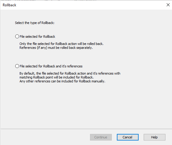
Figure 6: Individual or Reference Included Rollback

Once you have made your selection or are attempting to rollback a part, you will be presented with the window shown in Figure 7.

Figure 7: Rollback Window

Once you have entered your comments and you attempt to continue you will be presented with one final confirmation, making sure you know that all versions after the selected event will be permanently deleted. Check the selection that you understand and confirm the rollback.

Note: If you are working with various projects in different versions of SolidWorks this feature can be especially useful. If you accidentally save a project from an earlier version of SolidWorks to a more recent version, you can rollback to revert it back to a file type that works with whichever earlier version of SolidWorks it is you are working with.

That’s all for now! You now know how to navigate the version history provided in SolidWorks PDM. If you like the content or have questions, signup for our email list to stay in the loop for solutions or weekly content.

Written By: 

Creating Appearances in Visualize

Creating Appearances in Visualize

Have you come across an issue with SolidWorks Visualize where the exact desired appearance isn’t available in their wide variety of selections? Nothing is more satisfying than having what you imagine appear exactly as though in a final render. This blog will help to create inform readers on how to achieve these appearances!

What are Appearances?

In Visualize, appearances are the items that are applied to imported files or any models that are created in the software to aid them in appearing realistic. There is a large number of appearances already supplied by SolidWorks from the different type of wood finishes and metals to the more unique ones such as grass and soap bubbles. SolidWorks provides standard appearances that are saved when the software is installed, and they also have a cloud-based section that provides more custom appearances.

Different Types of Appearances

With SolidWorks Visualize Standard 2018, there are 15 different types of appearances that the user can create when creating their own. The correct selection will need to be chosen when deciding which is most applicable for the component it’s being applied to. This is fairly crucial because each of these will have a few to several different options for customizing the appearance. Some of these are simple such as the base color to more advanced like the density, roughness, and scattering of the color.


Figure 1: Examples of Appearance Options

Creating Custom Appearances

Since there are so many different options for creating appearances, for this blog we will be focusing on creating a generic appearance. To create a new appearance, first, navigate to the appearance tab, right-click within the window, and select New Appearance.


Figure 2: Creating a New Appearance


Next, select the drop-down arrow to Appearance Type and select the Generic option.

Figure 3: Selecting Generic Appearance

Compared to some of the other different appearance types, generic has many different customizing options. Below, is a brief explanation on each of these options.

  • Diffuse Color – the color that appears under white light
  • Specular Color – the colors on a shiny surface of the highlights that appear
  • Transparency Color – sets the model to appear see-through with a hint of color (good for glass and tinted glass)
  • Diffusion – adds a slight additional color to transparent colors
  • Emission – adds the color of light shown in the scene (good for users with Visualize Standard users that don’t have the option to directly add light)
  • Roughness – helps to either increase or decrease the reflectivity of the appearance
  • Internal Roughness – controls refracted light on the inside of the part rather than the surface
  • IOR (Index of Refraction) – controls transparently bent light going through the part
  • Color Density – the main thing here is the higher the number, the deeper the color will appear

Figure 4: Options in Generic Appearances

Conclusion

For creating custom colors that SolidWorks doesn’t provide in either the local library or cloud library, it’s best to get into the software and create your own. It can take some time to dial in exactly what each option does and what they’re capable of, but it becomes second nature with practice. These custom created appearances can be saved and then used on any future projects!

Importing Options for Visualize

Importing Options for Visualize

SolidWorks Visualize is a great software for creating realistic renderings of any company’s products quickly. The software is also able to import 20+ different file types from any SolidWorks parts and assemblies to STEP and STL files. This blog will mainly focus on importing options for SolidWorks parts and assemblies.

Import Files

Like most softwares, it’s simple to create and start a new project. Files can either be dragged straight in from something like a file explorer or directly from a downloaded web browser. The other way, which takes a couple of extra steps can be done just as easily. First a new project will need to be created and that’s completed by selecting the New Project button when first opening the software.

Figure 1: Starting a New Project

The next step is to select File from the main toolbar. Finally, select Import and locate the file you wish to render in Visualize.
 

Figure 2: File and Import

Import Types

Being that there is a wide variety of different file types that can be imported into Visualize, the specific import options will need to be catered to the file type. For instance, we would want to choose different import options between something like a 3D PDF and a regular SolidWorks part file. Below is a list of the different import options and a little information on each. The main thing to take away from this is that these options will determine which colors, appearances, and textures will carry over from the original files and it will determine how added colors from Visualize will appear whether it’ll attach to the entire part or just the surface.

  • Automatic – uses the best combination amongst all the import options to mimic the way the product is assembled in real life (Typically works well for all SolidWorks files).

  • Flatten – ignores all grouping and imports a single part. Component appearances can still be added to individual components without adding to the entire assembly.

  • Group/Appearance – more aimed towards Autodesk Alias .wire files as it retains the group hierarchy within the file, subdividing or subgrouping items based on the appearance, color, and group that is assigned.

  • Layer – imports based on which surfaces are assigned to layers within the CAD package, ignoring any appearance or color assigned. All surfaces assigned to each layer in the CAD file are imported as a single part.

  • Layer/Appearance – favors layers first, then appearance second to divide the model into parts.

  • Appearance – imports surfaces based on which are assigned the same color/appearance within the CAD package, ignoring any grouping or layering. All surfaces with the same color or appearance will be joined into a single part for quicker model painting.

  • Appearance/Layer – favors appearance first, then layers second to divide the model into parts.

  • Retain Structure – retains the raw hierarchy of the assembly model that is in the CAD package. This could yield many parts which will directly affect performance.

Figure 3: Import Settings

Conclusion

Not enough can be said at how great SolidWorks Visualize is as far as creating photo realistic photos and its ability to allow for many different file types to be imported. Always remember that when importing any file to double check the part grouping. This will be the main factor at determining how appearances and textures will be applied to the imported data!

Written By: 

3D Printing at Perception Engineering

3D Printing at Perception Engineering

If you have an idea for a product and possibly even the design ready to go, but you want to be able to have a better idea of what it may look like when it is manufactured, we have the solutions for you. One of those solutions is 3D printed prototyping.

Here at Perception Engineering, with both in-house capabilities and local partnerships, we can bring your prototype to life. This can often be done with one of the many forms of 3D printing. With our in-depth knowledge of printing processes, we can choose the best method for any project. In-house, we can carry out appropriate projects with FDM, otherwise known as Fused Deposition Modeling, which is the technique likely to come to mind when people hear 3D printing. This is where a thin layer of plastic is extruded out in layers in the shape of one’s product. An example of this product can be seen below.

 This can provide a great perspective into what your finished product will approximately look like when manufactured. Following are some samples of what a finished print may look like.


 If your product has features that fall outside of our in-house abilities, such as having extremely fine geometry and details, or you desire to have a production quality part with strong mechanical properties not done with FDM, we have 3D printing partners which we can work with to make sure the job is done right. We also have the knowledge to know what process will get the best results for any projects. To learn more about our in-house processes and some of the other commonly used processes that we have available to us through our partnerships, you can visit the 3D Printing page. 

Figure 1: Example 3D Printed Parts

That’s all for now! Keep us in mind for any of your current or future 3D printing prototyping needs. Every project has individual needs, and we can work with you to fit those needs. If you like the content or have questions, sign up for our email list to stay in the loop for solutions or weekly content.

Written By: 

SolidWorks: DriveWorks

DriveWorks

Repetitive tasks in SolidWorks have you down? Do you find yourself making the same design multiple times with small differences in features, size, and properties? DriveWorks is a unique design automation software that may be able to help! The best part about DriveWorks is that if you are already using SolidWorks the most basic version, Xpress is already built in. DriveWorks allows you to quickly and easily create and configure custom designs, using captured model or assembly information, desired logic, and user-defined parameters.  With the click of a button, this program will automatically generate assemblies, models, and drawings for the desired configuration.  To get a better understanding of where and how DriveWorks can be utilized, here are the basic procedural steps in setting up a program:

1.)    Capture Driven Elements: These are the variables you intend to drive the program with. At the core, this will include Dimensions, Features, Custom Properties and continue to expand with each DriveWorks product.

2.)    Create A Form: This is your user interface with the program. This tells the user what parameters they can control and collects the desired input from the user.

3.)    Apply Rules: This is where the logic of the program is defined; rather, the parameters from the user are tied together with the elements captured from SolidWorks.

4.)    Execute Program:  This is where the program automates the modeling and drawing process using the inputs from the user and the rules you defined with the click of a button. 

Figure 1: DriveWorks Interface

There are three options for DriveWorks that can be utilized with SolidWorks: Xpress, Solo, and Pro. While Xpress is already included in every license SolidWorks; Solo and Pro are the proceeding add-ons that cost $3,900 and $9,000, with customizable module options, correspondingly. Both Solo and Pro expand the capabilities of Xpress in terms of the extent of capturable elements, form customization, and I/O control. Pro takes it even further with an entire management and configuration system that can be geared towards both web and customer interface along with other company systems.

People often compare the capabilities of design tables with respect to DriveWorks. While design tables are very useful for certain applications DriveWorks excels when considering file size, ease of use, scalability, and automated capabilities. With DriveWorks new files are generated for each configuration as opposed to multiple configurations contained within one file. DriveWorks can also control parts, assemblies, and drawings without the need to update each design table or file individually. Using a DriveWorks form provides an easier and more efficient way for anyone (regardless of knowledge within SolidWorks) to configure files, and the rule-driven elements better link the desired configuration to implement all the changes to each assembly, part, and drawing.

Here at Perception Engineering we have experimented with projects using Xpress and are always looking for ways to utilize the capabilities of DriveWorks in providing a viable solution to our customers. The ability to configure and generate models rapidly and without requiring a user skillset in SolidWorks is a unique tool we can offer and provide.

Written By:

Virtual Reality: Headset Comparision

Virtual Reality Headset Comparison for Engineering Applications

With all of the different headset options currently out and many more upgrades on the way, a single location for some of the more popular virtual reality headsets can be very useful. This blog will hopefully serve many as the go-to location for comparing these headsets!

Headsets Being Compared

There is a wide variety of headsets currently being used, ones from $15 dollars made of cardboard to higher end ones that can cost up to $9000 dollars. For this blog, we will be comparing 5 different headsets. The headsets we will be comparing are the HTC Vive, HTC Vive Pro, Oculus Rift, Oculus Go (32GB), and the Google Cardboard. For each, we will look at some advantages to using each in engineering applications and some disadvantages to each.

Table 1: Headset Comparison Chart

HTC Vive

First, we’ll start with the main headset we have been using at Perception Engineering which is the HTC Vive. For the price and how simple the controllers are, this headset set is one of the better ones. With little to no experience, users can become experts with the controllers after running through the set-up process. In an engineering sense, the HTC Vive is great and one of the better headsets from the list. Many software recommends using the Vive because of its capabilities. All in all, it’s a great headset with a good price point for those getting started with virtual reality.


Figure 2: HTC Vive Headset

HTC Vive Pro


Next is the HTC Vive Pro which is similar to the basic HTC Vive, but it has some extra added benefits. One obvious change from the previous version is it’s upgraded headset design. This features built-in headphones and different strap methods so that wearing the headset for extended periods of time doesn’t cause pain. It also has a better resolution per eye giving the user a clearer view of whatever is being viewed. The only complaint so far with this headset is the price. The $799 headset does not include controllers or the base stations, so this is strictly for the headset itself. However, previous controllers and base stations from the original HTC Vive will work. Image by https://www.vive.com/us/product/vive-pro/

Figure 3: HTC Vive Pro Headset


Oculus Rift


For the price and specs of the Oculus Rift, it is up near the top as one of the better headsets to use. It’s a little cheaper than the HTC Vive but is identical as far as specs go. The controllers may look a little more complex than the HTC Vive controllers, but the Oculus Rift controllers are more comfortable as they are more ergonomically designed. This may not seem like an issue, but in extended uses, the more comfortable the better. One disadvantage with the Oculus Rift is the sensor tracking. For something like a 360-degree experience, a third tracker will need to be purchased. This can also be an advantage depending on the application. For bringing this technology to trade-shows, there isn’t the worries about needing an excessive amount of room since both trackers will be placed side-by-side facing the user. Image by https://www.oculus.com/rift/

Figure 4: Oculus Rift Headset

Oculus Go (32GB)

With a cleaner look and a more comfortable feel than that of the Oculus Rift, the Oculus Go is a great virtual reality headset for those just starting out with VR. This is another good headset for trade-shows as it is both wireless and only uses one controller. This is great for those who may not be up to date with the latest technology since there are very few buttons. There is a limit to what can be done with this headset. There is no room setup style so sitting down is the only option for viewing things virtually. There is still 360-degree viewing since the headset can track it all without the use of the tracking stations needed with the Oculus Rift and HTC Vive. At one of the lower prices of these headsets being compared, the Oculus Go should be highly considered by any company looking to implement virtual reality. Image by https://www.oculus.com/go/


Figure 5: Oculus Go Headset

Google Cardboard

The Google Cardboard has been added to this list even though it’s not really virtual reality, but rather it’s a 360-degree viewing experience. This doesn’t mean that it’s not useful for certain engineering applications. For it is the lowest cost and wireless, it’s very useful for viewing something like CAD files in a virtual environment right on a smartphone. Being that it’s on a smartphone, there is a limit to how large and detailed some items can be. This may be tricky for certain applications or companies where detail is very important. 360-degree photos for quickly showing someone is where the Google Cardboard really stands out from the rest. It’s very quick to take a 360-degree photo, load it on a smartphone, and then view it in the headset. This is ideal in a setting where many individuals will be looking at the same photo because they won’t be able to interact with items as in-depth as they could with one of the other headsets. The biggest takeaway here is that the Google Cardboard is quick, lower cost, and easy to use.


Figure 6: D-Scope Google Cardboard 360-Degree Viewer

Conclusion

In the end, it’s all up to company specifics as to which headset to go with. At Perception Engineering, we use the HTC Vive, but there wouldn’t have been any issues if we would have gone with the Oculus Rift for instance based strictly on specs of the headsets. The HTC Vive Pro is just too early to purchase. Even with us having the earlier version and having both the controllers and base stations work with it, it’s better to wait until the full HTC Vive Pro package can be bought in one bundle. For quickly showing files such as a 360-degree photo of a product that’s trying to be sold,

for instance, the Google Cardboard and Oculus Go are great options. Again, the best approach is to check the company’s overall goals and pick the most applicable headset!

Written By: 

SolidWorks: Weldments

Weldments

Weldments are a staple in the machining and design field. Designing a weldment frame one tube at a time in SolidWorks could take hours on end, only to have the design change almost immediately. Thankfully SolidWorks offers a faster way. The Weldments tab/tools allow for quick building and trimming of weldment structures by using a simple sketch. This blog will be over some of the basics of Weldments in SolidWorks.

Weldments Tab Location

All weldment tools can be found in the weldment tab while creating a part. Sometimes the tab will not be present on the toolbar, all that needs to be done to make it available is to right click on any other tab and select the weldments option. Once the weldments option is selected a weldments tab will appear on the toolbar. Also, weldment tools can be found under the insert drop down menu. The weldments tab location is shown below in Figure 1.


Figure 1: Weldments tab location

How to input weldments

To input any weldments, a sketch is needed for a profile. Weldments can be put on both regular and 3D sketches. However, it is much easier to do this by using 3D sketches. An entire welding table can be put together by using one 3D sketch. A 3D sketch can be started simply by clicking the 3D sketch button located on the weldments tab. Once the button is selected, click on the line command and choose a starting point in the drawing area, no starting plane is needed.  Next to the cursor will be the letters XY, YZ, or XZ. These letters represent the 3D direction the line will be placed in. The direction of the line can be changed by hitting the tab button. The change in direction will also be shown by the red origin arrows that appear when creating a 3D sketch. For weldments to be placed on a sketch it must be made of straight lines, no arcs or circles. An example of starting a 3D sketch is shown in Figure 2.

Figure 2: Starting a 3D sketch

Selecting the Type of Weldment

Once the desired structure shape has been created with a 3D sketch make sure all lines are fully defined and exit the sketch. Next, Click on the Structural member command on the weldments tab. Once the tool is selected there will be three drop-down menus inside the property manager to select the correct type of weldment for the job. Under the standard selection menu, either metric or ANSI inch can be chosen. Depending on what standard is chosen, some different types of weldment tubes will be shown.

Under the type drop-down menu, the different tubes can be selected. And finally, under the size drop-down menu, all sizing for the selected types of weldments will be shown. For this blog, 2” X 2” square tube will be used. The menus are shown in Figure 3 below.

Figure 3: Weldment drop-down menus

Once the Weldment type is selected it is time to start putting together groups. Weldments can only be placed into a drawing in groups, these groups must be lines that are on the same flat plane. For example, a weldment group can be on lines that are all in the XY linear direction, but not the XY and YZ direction. To input weldments onto a new line direction, the “New Group” button can be pressed into the property manager and the new group of lines can be selected. In Figure 4 below, an example of weldment groups is shown. Group1 is the top level square tubes of the table while Group2 is the square tube legs for the table.

Figure 4: Weldment group example

Corner Treatment

There are three corner options to choose from when inputting weldments. There is a mitered corner, inside end butt, and outside end butt. By selecting the corner option in the property manager, it will change all corners of the selected group. To change an individual corner, select a group then zoom in onto the one desired corner to change. There will be a small purple dot in the corner joint where the two weldments meet. If the purple dot is double-clicked, that individual corner can be changed. These options are shown in Figure 5.

Figure 5: Corner treatment options

Trimming and Extending Weldments

After the weldments have been placed into groups on the line sketch, there is a way to clean up some of the tubes if they did not come out right at joints and intersections. Sometimes, the end of a tube may not meet up flush to a corner or maybe the desired outcome is to have the tube wrap around parts of the intersecting tube. These types of options can be controlled through the trim/extend command in the weldments tab. The location of the trim/extend command is shown in Figure 6.

Figure 6: Trim & Extend command location

Once the trim/extend command is selected, the first option in the property manager is the corner type. The types to choose from are End trim, End miter, End butt1, and End butt2. After selecting the type of corner desired to trim to, there are two selection boxes for bodies/faces. The top selection box is to choose what bodies to trim, the other is the face/plane or bodies that will be the trimming boundaries. At the very bottom of the property manager is the option to do a simple cut or a coped cut. The coped cut will cause a sort of wrapping to the tube at the end to wrap around the tube it is intersecting with. An example of a tube being trimmed to be flush with the top of the upper-level tubes is shown in Figure 7.  

Figure 7: Trim & Extend example

Things to look out for

When first putting the tubes into the sketch it almost must be done like a puzzle to have them go in the way desired. Be sure to think of how the pieces would really fit together and put them into the sketch in that group order. When inputting some tubes into the sketch they can come in twisted and not centered to their intersecting tubes. This can be corrected by entering an angle value into the angle input box under the alignment section inside the property manager. 

Final Thoughts

Overall, the Weldment tab/tools available in SolidWorks can be used to quickly create and assemble both basic and complex weldment structures saving time. Using the powerful tools at hand in SolidWorks can help edit previously made structure as well, allowing for quick updating of changed designs. With the fast-moving pace of today’s work, the knowledge of how to use these tools effectively is a must and it will have a clear impact once a project has been completed.

Written By:

SolidWorks: Mass and Measuring Evaluations

SolidWorks: Mass and Measuring Evaluations

In this blog, we will be discovering the mass and measuring evaluations within SolidWorks. These tools are useful in determining the size and weight of a particular part or assembly. We will be looking at how to use these tools, as well as some applications in which they may become useful.

Measure

The measuring tool allows users to calculate the distance between selected items, points, faces, etc.. The measuring tool can be found on the evaluate tab shown below:


Figure 1: Measuring Tool

You can also find the measuring tool by going to Tools > Evaluate > Measure…:

Figure 2: Measuring Tool File Location

Once the measuring tool is open, the pop-up window should look like the image below:

Figure 3: Measuring Tool Window

The first icon in the measuring window pulls up a menu for Arc/Circle Measurements. The list below allows the user to select their desired measuring format between circles and arcs.

Figure 4: Measuring Tool Features

The second icon in the measuring window opens the Measure Units/Precision window. The measure units/precision window allows the user to set the preferences for the desired units (imperial or metric), scientific notation, decimal or fractions, number of decimal places or denominator, and dual dimensions.

Figure 5: Measuring Units/Precision

The third icon allows you to enable/disable the XYZ measurements within the part/assembly window.

Figure 6: XYZ Measurements

With this feature selected the measurements in each direction are visible similar to the blue and red lines below, indicating the X and Z measurements, in this case. If this feature was not selected, only the black line would be shown, indicating the overall distance measured.

Figure 7: Directional Measurements

The fourth icon, called point-to-point, allows the user to measure the distance between two click points. Without this feature selected, the measuring tool would measure the features of the face selected and output dimensions such as the area, perimeter, etc..

Figure 8: Point-to-Point Measurement

Mass Properties

The mass properties of a part or assembly can be found by going to the evaluate tab and clicking on the icon labeled Mass Properties.

Figure 9: Mass Properties

The mass properties of a part/assembly can also be found by going to Tools>Evaluate>Mass Properties as shown below.

Figure 10: Mass Properties File Location

Once the Mass Properties window pops up, a variety of information can be found. Within the mass properties window the density, mass, volume, surface area, the center of mass, and moment of inertia can be determined. Within the window, you also have the option to select which coordinate system these values are taken from.

Figure 11: Mass Properties Window

The evaluate features discussed in this blog are very useful tools. One example of how the measuring tool and mass properties can be used, is by aiding in determining the box size and the shipping cost of a component once the weight is known. They can also be used to help hit design requirements that are determined by specific dimensions or weight specifications  

That’s all for now! You now know the basics of SolidWorks Evaluations. If you like the content or have questions, signup for our email list to stay in the loop for solutions

Written By:

Why Use Virtual Reality

Why Use VR

Known mainly in the gaming world, virtual reality is making itself more and more noticeable and useful in other applications. One application we’ve been using virtual reality for is its usefulness in the engineering world. This blog will describe some reasons to use virtual reality!

What is Virtual Reality?


Before describing why use virtual reality, we will touch on what it is exactly. Basically, it’s a 3D computer generated image that allows the user, with the help of some extra viewing equipment, the ability to interact in a more personal manner with the generated creation. This can be things such as getting a true 1:1 scale compared to the user or actually grabbing items and interacting with them.


Figure 1: Accurate Model Scale

Benefits to Using VR

At first glance, virtual reality may just seem like a gimmick and that it’s not something that should be associated with things such as engineering or architectural work. However, this is not the case as there are many things that can be done! The best part is that technology is changing every day and the advancements are only making the case to use it stronger.

One benefit being it helps to save both time and money on designs. It prevents going from the CAD phase to the prototyping phase only to realize that it didn’t come out as intended and end up with wasted money on the design. Virtual reality helps to bridge the gap between these two phases by allowing the user to get the 1:1 scale, see how components sit in the assembly, and ensure that the end design is ready to be manufactured.


Figure 2: Bridge Between CAD and Prototype


With the time in mind, virtual reality aids with communicating clear design solutions to projects. While looking at a model on a screen or on a drawing, people might see different things or not even understand what they may be looking at. Virtual reality gives everyone the same exact view. In some instances, with certain softwares, models can be marked up in a way that will aid in adjustments further down the design process.


Figure 3: Markup in Models

Another benefit comes with plant floor layouts and ensuring safety before going in and moving equipment. Rather than having to tie three people up to move equipment around only to realize that the selected location won’t work, it’s possible to have just one person using only one hand to move equipment around with virtual reality. We at Perception Engineering used this capability to help with deciding the layout of the office. We were able to grab each piece of furniture like desks and chairs and place them in a way that would satisfy both our needs and increase work efficiency.

Figure 4: Office Layout

Conclusion

Advancements in technology with virtual reality are changing every day. It’s a process many people are not even aware of or know little about. There is no limit to what can be done virtually. Many of the tasks done currently will be completely different whether it’s something with designing components, quoting, or even meetings. Virtual reality is aiding in connecting people around the world for a more connected future.

Written By: 

Lighting in Visualize

Lighting in Visualize

With each package of SolidWorks Visualize there are some things you can and can’t do from one to the next. This blog will focus mainly on one little issue that we’ve run into at Perception Engineering when it comes to the lighting aspect of models and some of the tips and tricks we use to overcome them.

Visualize Packages

With each seat of SolidWorks Professional and Premium, a seat of SolidWorks Visualize Standard is included. SolidWorks Visualize Standard and Professional can also be purchased separately. This benefits non-SolidWorks users because not only is it a standalone product, but with the ability to add in over 20 different file types, it’s hard not to justify the cost for this software.

Steps to Adding Lights

Being that we use Visualize Standard, there is no option to add a light directly, so we have to do some work around to create an emissive appearance that will give the view of light. Luckily, there is an easy way to do this! The first task is to create a New Project in Visualize and import the model based on how appearances are to be applied. For more information on this, please visit the Importing Options for Visualize blog. Once this is complete, the next step is to apply appearances to the components. For our example, I created a table with a couple of objects sitting on top inside of SolidWorks. I then added it to Visualize and started applying some of the appearances.


Figure 1: Table and Objects with Appearances

Next, being that it is a desk lamp, we want it to have the appearance of having a light bulb inserted and shining on the table. This is completed by going up to the project tab, selecting models, and a model to act as the light. Alternatively, right-clicking the palette and selecting new model will add in a new primitive object.

Figure 2: Adding New Models

Now that the model has been created, we need to position it in the place we want the light to appear at. For this example, we also added a circle model to the table to show where the light will hit. To adjust the position and the scale of these items, first select them and then we will be using the HUD to manipulate them.

Figure 3: Manipulating Models

Once these are in the correct positions, we will need to give them an emissive appearance. This can be achieved by going to the File Libraries tab and selecting emissives.

Figure 4: Emissives Appearance Folder

Now, drag something like the white light appearance to the models created earlier. This next step is important to remember to do. If this step is skipped, the models with the emissive appearances will appear as a flat white rather than appearing like a true light. Go to the Models tab, select one of the primitive models, and navigate to the general tab below. The two option we need selected are Visible and Faded. These will leave the lights there while hiding the models giving an accurate appearance to the desk lamp.

Figure 5: Visible and Faded Options

The model is now ready for rendering! Here is the final render of our desk with a couple of objects on it. Notice the created models are hidden, but the light remains. This can be done with any type of light or if some light is needed in an area that is a little too dark.

Figure 6: Final Render with Added Lights

Conclusion

All-in-all, even though it’s a couple of added steps to add lights into a render, these will help give them a more realistic appearances overall. Just because there isn’t an easier way to add lights doesn’t mean that it can’t be done. It may be tricky to orient the added models at first, but with practice these steps will take just minutes!

Written By: