Creating Appearances in Visualize

Creating Appearances in Visualize

Have you come across an issue with SolidWorks Visualize where the exact desired appearance isn’t available in their wide variety of selections? Nothing is more satisfying than having what you imagine appear exactly as though in a final render. This blog will help to create inform readers on how to achieve these appearances!

What are Appearances?

In Visualize, appearances are the items that are applied to imported files or any models that are created in the software to aid them in appearing realistic. There is a large number of appearances already supplied by SolidWorks from the different type of wood finishes and metals to the more unique ones such as grass and soap bubbles. SolidWorks provides standard appearances that are saved when the software is installed, and they also have a cloud-based section that provides more custom appearances.

Different Types of Appearances

With SolidWorks Visualize Standard 2018, there are 15 different types of appearances that the user can create when creating their own. The correct selection will need to be chosen when deciding which is most applicable for the component it’s being applied to. This is fairly crucial because each of these will have a few to several different options for customizing the appearance. Some of these are simple such as the base color to more advanced like the density, roughness, and scattering of the color.


Figure 1: Examples of Appearance Options

Creating Custom Appearances

Since there are so many different options for creating appearances, for this blog we will be focusing on creating a generic appearance. To create a new appearance, first, navigate to the appearance tab, right-click within the window, and select New Appearance.


Figure 2: Creating a New Appearance


Next, select the drop-down arrow to Appearance Type and select the Generic option.

Figure 3: Selecting Generic Appearance

Compared to some of the other different appearance types, generic has many different customizing options. Below, is a brief explanation on each of these options.

  • Diffuse Color – the color that appears under white light
  • Specular Color – the colors on a shiny surface of the highlights that appear
  • Transparency Color – sets the model to appear see-through with a hint of color (good for glass and tinted glass)
  • Diffusion – adds a slight additional color to transparent colors
  • Emission – adds the color of light shown in the scene (good for users with Visualize Standard users that don’t have the option to directly add light)
  • Roughness – helps to either increase or decrease the reflectivity of the appearance
  • Internal Roughness – controls refracted light on the inside of the part rather than the surface
  • IOR (Index of Refraction) – controls transparently bent light going through the part
  • Color Density – the main thing here is the higher the number, the deeper the color will appear

Figure 4: Options in Generic Appearances

Conclusion

For creating custom colors that SolidWorks doesn’t provide in either the local library or cloud library, it’s best to get into the software and create your own. It can take some time to dial in exactly what each option does and what they’re capable of, but it becomes second nature with practice. These custom created appearances can be saved and then used on any future projects!

Importing Options for Visualize

Importing Options for Visualize

SolidWorks Visualize is a great software for creating realistic renderings of any company’s products quickly. The software is also able to import 20+ different file types from any SolidWorks parts and assemblies to STEP and STL files. This blog will mainly focus on importing options for SolidWorks parts and assemblies.

Import Files

Like most softwares, it’s simple to create and start a new project. Files can either be dragged straight in from something like a file explorer or directly from a downloaded web browser. The other way, which takes a couple of extra steps can be done just as easily. First a new project will need to be created and that’s completed by selecting the New Project button when first opening the software.

Figure 1: Starting a New Project

The next step is to select File from the main toolbar. Finally, select Import and locate the file you wish to render in Visualize.
 

Figure 2: File and Import

Import Types

Being that there is a wide variety of different file types that can be imported into Visualize, the specific import options will need to be catered to the file type. For instance, we would want to choose different import options between something like a 3D PDF and a regular SolidWorks part file. Below is a list of the different import options and a little information on each. The main thing to take away from this is that these options will determine which colors, appearances, and textures will carry over from the original files and it will determine how added colors from Visualize will appear whether it’ll attach to the entire part or just the surface.

  • Automatic – uses the best combination amongst all the import options to mimic the way the product is assembled in real life (Typically works well for all SolidWorks files).

  • Flatten – ignores all grouping and imports a single part. Component appearances can still be added to individual components without adding to the entire assembly.

  • Group/Appearance – more aimed towards Autodesk Alias .wire files as it retains the group hierarchy within the file, subdividing or subgrouping items based on the appearance, color, and group that is assigned.

  • Layer – imports based on which surfaces are assigned to layers within the CAD package, ignoring any appearance or color assigned. All surfaces assigned to each layer in the CAD file are imported as a single part.

  • Layer/Appearance – favors layers first, then appearance second to divide the model into parts.

  • Appearance – imports surfaces based on which are assigned the same color/appearance within the CAD package, ignoring any grouping or layering. All surfaces with the same color or appearance will be joined into a single part for quicker model painting.

  • Appearance/Layer – favors appearance first, then layers second to divide the model into parts.

  • Retain Structure – retains the raw hierarchy of the assembly model that is in the CAD package. This could yield many parts which will directly affect performance.

Figure 3: Import Settings

Conclusion

Not enough can be said at how great SolidWorks Visualize is as far as creating photo realistic photos and its ability to allow for many different file types to be imported. Always remember that when importing any file to double check the part grouping. This will be the main factor at determining how appearances and textures will be applied to the imported data!

Written By: 

Lighting in Visualize

Lighting in Visualize

With each package of SolidWorks Visualize there are some things you can and can’t do from one to the next. This blog will focus mainly on one little issue that we’ve run into at Perception Engineering when it comes to the lighting aspect of models and some of the tips and tricks we use to overcome them.

Visualize Packages

With each seat of SolidWorks Professional and Premium, a seat of SolidWorks Visualize Standard is included. SolidWorks Visualize Standard and Professional can also be purchased separately. This benefits non-SolidWorks users because not only is it a standalone product, but with the ability to add in over 20 different file types, it’s hard not to justify the cost for this software.

Steps to Adding Lights

Being that we use Visualize Standard, there is no option to add a light directly, so we have to do some work around to create an emissive appearance that will give the view of light. Luckily, there is an easy way to do this! The first task is to create a New Project in Visualize and import the model based on how appearances are to be applied. For more information on this, please visit the Importing Options for Visualize blog. Once this is complete, the next step is to apply appearances to the components. For our example, I created a table with a couple of objects sitting on top inside of SolidWorks. I then added it to Visualize and started applying some of the appearances.


Figure 1: Table and Objects with Appearances

Next, being that it is a desk lamp, we want it to have the appearance of having a light bulb inserted and shining on the table. This is completed by going up to the project tab, selecting models, and a model to act as the light. Alternatively, right-clicking the palette and selecting new model will add in a new primitive object.

Figure 2: Adding New Models

Now that the model has been created, we need to position it in the place we want the light to appear at. For this example, we also added a circle model to the table to show where the light will hit. To adjust the position and the scale of these items, first select them and then we will be using the HUD to manipulate them.

Figure 3: Manipulating Models

Once these are in the correct positions, we will need to give them an emissive appearance. This can be achieved by going to the File Libraries tab and selecting emissives.

Figure 4: Emissives Appearance Folder

Now, drag something like the white light appearance to the models created earlier. This next step is important to remember to do. If this step is skipped, the models with the emissive appearances will appear as a flat white rather than appearing like a true light. Go to the Models tab, select one of the primitive models, and navigate to the general tab below. The two option we need selected are Visible and Faded. These will leave the lights there while hiding the models giving an accurate appearance to the desk lamp.

Figure 5: Visible and Faded Options

The model is now ready for rendering! Here is the final render of our desk with a couple of objects on it. Notice the created models are hidden, but the light remains. This can be done with any type of light or if some light is needed in an area that is a little too dark.

Figure 6: Final Render with Added Lights

Conclusion

All-in-all, even though it’s a couple of added steps to add lights into a render, these will help give them a more realistic appearances overall. Just because there isn’t an easier way to add lights doesn’t mean that it can’t be done. It may be tricky to orient the added models at first, but with practice these steps will take just minutes!

Written By: 

Visualize: Photo Quality Renders

Photo Quality Renders with SolidWorks Visualize

Imagine being able to produce photo quality renders in just minutes without the cost of creating the item in the real world! This blog will introduce you to the powerful, fast world of SolidWorks Visualize and some of the capabilities of the software.

Visualize Introduction

SolidWorks Visualize is a rendering software that was introduced a couple of years ago to users as one of the first standalone software tools to create realistic renders through SolidWorks. Visualize is well known in the industry for the quality renders it’s able to create.

How to Create a New Project

SolidWorks has made creating projects in Visualize very simple from the import process to saving off a final render. One of the first screens that will appear will have tabs set up to view recently worked on projects, some provided sample projects, and recent documents opened within SolidWorks. For creating a new project, it’s as simple as selecting the New Project option highlighted in yellow in Figure 1 below.

Figure 1: Initial Interface

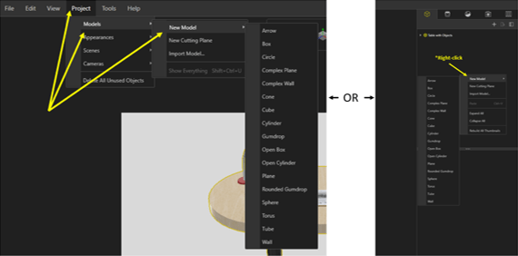
The next step to reaching a photo quality render is to import the desired file with the model to be worked on. Visualize allows the import of many different file types into a new project from SolidWorks files to SketchUp files and 18 others! There are two different ways to import a file into Visualize. The first is to go through the File tab in the top left corner of the screen and select Import from the dropdown list (the same as hitting Ctrl+I). The second way to import a file is to grab it from the folder it is currently in and drag and drop it into the Visualize interface.

Figure 2: Importing Files

After the selected file has been imported into Visualize, an import settings window will appear and allow the user to define what happens to the imported file. These options will vary from person to person as to how they want the file imported. It depends on the size of the imported file, how many components there are in an assembly, and things of that nature. There is also the ability to deselect some of the import setting tabs if none of this information is needed for the final render.

Figure 3: Import Settings

Now, we will describe each tab with a basic overview of what each is trying to accomplish.

  • Geometry – the focus of this tab is to decide how the imported files will act. You can choose to have the entire imported file change colors/position at once, or it can be refined to allow each individual component of an assembly gets its own color or to move independently from the rest.

  • Appearance – source model appearances can carry over from the original file if desired. There is also the option to locate the missing textures and to add specified paths for textures.

  • Cameras – any saved camera views from the original SolidWorks CAD file can be carried over from the SolidWorks software as well as animated cameras from FBX file formats.

  • Scene – this tab allows to either enable or disable imported environments or backplates from the SolidWorks file.

  • Decals – this tab allows for the option to import decals from the original SolidWorks CAD file.

Adding Colors to the Model

Once everything has been imported into Visualize, there is now the part where creativity takes over! There are many options as far as what sort of color that can be added to the model, from basic, flat colors to more complex appearances such as a soap bubble appearance to heat treated titanium. One thing to notice is up in the top-right corner there are two tabs: one saying local and the other saying cloud. The local appearance tab is full of appearances that are that are included with the downloaded software. There are still many options for appearances that can be used with this. The cloud appearance tab allows the user the ability to select any appearance or color from the full online library as well as the local appearances. The cloud appearance tab is where many of the more unique options will be located.

Figure 4: Appearances

SolidWorks has made the process of adding colors to the model very simple and easy to do. Once the desired appearance has been located from the palette, all that is needed is to click and drag the appearance to the specific part of the model to apply that specific color. If the chosen appearance isn’t quite correct, there is also the option to adjust and refine them to get the exact desired color. There is an included color picker to select a color from anything on the screen. Also included are sliders to manually go through and slide through all the colors. If the custom created color is something that can be used for other projects, there is the option to save it in a user-specified folder for use later. This is done by selecting the ‘Export’ option in the top-right corner and selecting ‘Save Appearance’.

Figure 5: Custom Appearances

Creating the Final Render

With all the appearances applied and the model all squared away, the final render can now be created to show-off the photorealistic renders. This can be done by selecting the output tools tab at the top-center of the screen.

Figure 6: Output Tool for Final Render

There are many different options to create the final render such as choosing the size of the end photo, the resolution, and whether the software will use the CPU, GPU, or a hybrid of the two. First, select the file name and then map which folder the final render will be saved in. Next is choosing the image format. There are things like if the file is to be saved as JPEG, a BMP, or something like a PNG. No matter which option is selected for the size, the software will scale the photo simultaneously to prevent the size from being too wide or too tall and thus preventing the final render from being out of proportion. Right below size is the resolution option, which determines how many pixels there will be per inch or per centimeter depending on which option is selected. One general rule here is the higher the resolution, the smoother the image will be in the end. Finally, the last options to be adjusted are the render settings. The renderer selection gives three options to how the final render will appear; preview being the lowest quality, fast being a little better than the preview, but not the best, and accurate which will yield the best results. Render mode will only appear if the accurate mode is selected. Render mode allows the user to choose whether they want to set a certain number of passes with the quality option or if they want to set a time limit.  For the quality option, however, many passes that are inserted, the software will continually do a render pass no matter how long the time until that final number is reached. The time limit allows the user to set a certain amount of time and when the time is hit, the render will stop no matter the quality at that time.

Figure7: Output Tools

Summary

With all this being said, you now have the tools and basic abilities to create these high-quality photos for marketing your product, helping pitch your design, and just creating cool photos to show friends and coworkers. It may take some time to get everything dialed in to show exactly what is intended, but with time these renders can be created quicker and better than before.

Figure 8: Final Render

Written By: